


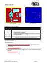

ZXLD1350EV2
ZXLD1350EV2 User Guide Iss 5 10-04-07
Low Frequency PWM Dimming
1. Switch off the power supply.
2. Solder a link across R1 pads.
3. Make sure C3 is not fitted.
4. Connect a PWM signal to the ADJ pin via an open collector NPN transistor or an open drain N-channel
MOSFET.
5. Alternatively, drive the ADJ pin directly with a PWM signal. However, make sure the PWM signal voltage
levels do not violate the ADJ pin voltage rating. Driving the ADJ pin above 1.25V will exceed the maximum
set current for the value of Rs and may damage the device or LED
6. The PWM frequency can be low; around 100Hz or up to 1kHz.
7. The ZXLD1350 is now effectively being turned on and off at the PWM frequency. The dimming ratios are in
the region of 100:1, much greater than the DC dimming ratio. The average l LED current (output current),
I
OUT,
is given by
I
OUT
= 0.1*D/Rs where I
OUT
= the average LED current.
Rs = the sense resistor value in ohms.
Do not use a resistor value lower than 0.27Ω.
D = the duty cycle of the PWM dimming frequency.
0.1V is the nominal sense voltage with ADJ open circuit or set to 1.25V.
8. Follow the ‘ZXLD1350EV2 Power Up’ sequence.
Soft-start
1. Switch off the power supply.
2. Solder a link across R1 pads.
3. Fit a capacitor at C3 to decouple the pin. The value of C3 will determine the soft-start time setting. Please
see the datasheet for calculation of the capacitor value.
4. Follow the ‘ZXLD1350EV2 Power Up’ sequence.
Switching the output current off
1. Switch off the power supply.
2. Solder a link across R1 pads.
3. Follow the ‘ZXLD1350EV2 Power Up’ sequence.
4. Connect the ADJ pin to GND to turn off the output current.
5. Follow the ‘ZXLD1350EV2 Power Up’ sequence. The ZXLD1350 internal switch remains switched off (output
current off) whilst the ADJ pin is pulled to GND.
Changing the LED current
1. Switch off the power supply.
2. Remove Rs.
3. Calculate and fit a new sense resistor, Rs, the value of which is based on the required LED current without
dimming. Rs can be calculated using following equation :
Rs = 0.1V/I
OUT
where I
OUT
= the LED current.
Rs = the sense resistor value in ohms.
Do not use a resistor value lower than 0.27Ω.
0.1V is the nominal sense voltage with ADJ open circuit or set to 1.25V.
4. Follow the ‘ZXLD1350EV2 Power Up’ sequence.
Using external LEDs or loads
1. Switch off the power supply.
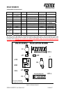
2. Connect external LEDs across test pins ‘LED a’ and ‘LED k’. ‘LED a’ is the LEDs' anode connection point
and ‘LED k’ is the LEDs' cathode connection point. The number of external LEDs that can be connected
depends on their operating power and forward voltage drop. For an external load other than LEDs, the
positive terminal of the load should be connected to test pin ‘LED a’ and the negative terminal of the load
should be connected to test pin ‘LED k’. Connector J1 is compatible with the ‘Luxeon® Emitter Board
System’ from Future Electronics, or can be used to connect LEDs via pin-strip connectors.
3. Follow the ‘ZXLD1350EV2 Power Up’ sequence.