


ZXLD1350EV2
ZXLD1350EV2 User Guide Iss 5 10-04-07
OTHER FEATURES
Dimming
The ZXLD1350 provides three dimming options: DC, high-frequency PWM, and low-frequency PWM dimming.
DC Voltage Dimming
1. Switch off the power supply.
2. Solder a link across R1 pads.
3. Fit a 10nF capacitor at C3 to decouple the pin.
4. Drive the ADJ pin on the board with a DC voltage in the range 0.3V to 1.25V.
5. Do not exceed 1.25V, as this represents 100% of the LED current set by Rs. The current will increase in
proportion to this voltage. For example, if 2.5V is applied, the current will increase to 200%. That is, the
current will be twice the 1.25V rating. For such over-drive of the ADJ pin, the LED and ZXLD1350 are likely
to be damaged. The nominal LED current (output current), I
OUT
, is given by
I
OUT
= 0.08* V
ADJ
/Rs where I
OUT
= the nominal LED current.
V
ADJ
= the DC dimming voltage at ADJ pin resistor.
0.08 is the multiplier for the reference voltage on ADJ pin.
Rs = the sense resistor value in ohms.
Do not use a resistor value lower than 0.27Ω.
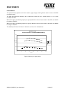
6. The dimming ratio is around 6:1. Note: as the voltage approaches 0.2V on the ADJ pin, the ZXLD1350 will
shut down.
7. Follow the ‘ZXLD1350EV2 Power Up’ sequence.
High Frequency PWM Dimming
1. Switch off the power supply.
2. Solder a link across R1 pads.
3. Ensure C3 is not fitted.
4. Connect a PWM signal to the ADJ pin via an open collector NPN transistor, or an open drain N-channel
MOSFET.
5. Alternatively, drive the ADJ pin directly with a PWM signal. However, make sure the PWM signal voltage
levels do not violate the ADJ pin voltage rating. Driving the ADJ pin above 1.25V will exceed the maximum
set current for the value of Rs and may damage the device or LED.
6. Set the PWM frequency to between 10KHz and 50KHz. The cut-off frequency of the internal filter is 4kHz,
and exceeding the 50kHz may cause modulation with the switching regulator.
7. The dimming ratio will be about 6:1, similar to the DC dimming. The nominal LED current (output current),
I
OUT,
is given by
I
OUT
= 0.1*D/Rs where I
OUT
= the nominal LED current.
Rs = the sense resistor value in ohms.
Do not use a resistor value lower than 0.27Ω.
D = the duty cycle of the PWM dimming frequency.
0.1V is the nominal sense voltage with ADJ open circuit or set to 1.25V.
Note: The ADJ pin is internally referenced to 1.25V. This pin should be left floating for normal operation
without dimming. Please refer to the datasheet for PWM frequency.
8. Follow the ‘ZXLD1350EV2 Power Up’ sequence.