


ZXLD1350EV2
ZXLD1350EV2 User Guide Iss 5 10-04-07
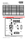
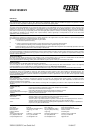
U1
+VIN
GND
ADJ
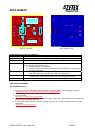
ZXLD1350EV2 EVALUATION BOARD
Bare board: ZDB308R3
L1
SD1
JP2
C3
Copyright Zetex Plc 2006
a
k
a
k
a
k
R1
JP3
JP1
LED a
LED k
RS
C1
C2
R2
In partnership with:
D1
D2
D3
1
J1
Figure 4: Top View Figure 5: Bottom View
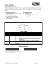
ZXLD1350EV2 Connection Point Definition
Name Description
+VIN Positive supply voltage. Connect a +24V positive supply to this pin.
GND
Supply Ground (0V). Connect supply ground to this pin.
ADJ Internal voltage ref. pin (1.25). This pin can be used to achieve dimming and soft-start,
and for switching the output current off.
• Leave floating for normal operation.
• See 'Other Features' section to achieve dimming, and soft-start and for switching
the output current off.
LED a LED a connects to the ANODE of LED D3, and is the external LED anode connection
point. Disconnect the jumper JP2 when driving an external load.
LED k LED k connects to the CATHODE of LED D1, and is the external LED cathode
connection point. Disconnect the jumper JP2 when driving external LEDs.
J1 Pins 1 & 2: LED a, Pins 5 & 6: LED k
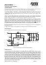
ZXDL1350EV2 OPERATION
ZXLD1350EV2 Power Up
1. Connect VIN to +24V of the power supply unit (PSU). Connect GND to the power supply ground (0V).
Warning: The board does not feature reverse battery/supply protection.
2. Set the PSU to +24V. (+24V at VIN pin with ref. to the GND pin.)
3. Turn on the PSU.
Warning: Do not stare at the LEDs directly.
4. Ensure jumper J2 is fitted. With JP1 and JP3 disconnected (jumper off), all three LEDs should illuminate and
will be regulated nominally at 300mA.
5. To change the number of LEDs connected in series, use jumper JP1 and JP3 to bypass LEDs D1 and D3
respectively.
Warning: The LEDs may be hot.