


ZXLD1350EV2
ZXLD1350EV2 User Guide Iss 5 10-04-07
ZXLD1350EV2 EVALUATION BOARD USER GUIDE
DESCRIPTION
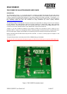
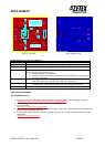
The ZXLD1350EV2, Figure 1, is an evaluation board for evaluating the ZXLD1350 350mA LED driver with internal
switch. The evaluation board can be used to drive 1, 2 or 3 one-watt LEDs, or an external choice of LEDs. The
number of external connected LEDs depends on the forward voltage of the LEDs connected. A connector, J1, is
provided, which is compatible with the modular evaluation system used by Future Electronics Ltd. The LEDs fitted on
this evaluation board are from the LUXEON ® range distributed by Future Lighting Solutions
(www.FutureLightingSolutions.com
)
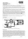
The operating voltage is nominally 24V. For three 1W series-connected LEDs, the voltage can be from 12V minimum
to 30V maximum. The 100uH inductor used in the circuit is based on a nominal 24V supply, which should be
connected across +VIN and GND pins. Note: The evaluation board does not have reverse battery protection. The
nominal current for the evaluation board is set at 300mA with a
0.33Ω sense resistor, Rs.
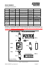
Jumpers J1, J2 and J3 allow the selection of the number of LEDs to be connected in series. Jumper on at J1
bypasses LED D1. Jumper on at J3 bypasses LED D3. Removing jumper J2 disconnects all the on-board LEDs from
the current flow path. Jumper 2 also doubles as a connection point for an ammeter to measure the LED current.
Before connecting external LEDs across test pins LED+ and LED-, or across J1, remove jumper J2. Jumpers J1 and
J2 can be on or off.
Test point ADJ provides a connection point for DC or PWM dimming and shutdown.
Warning: At 24V nominal operation with 300mA output, the LEDs and the PCB may be hot and the LEDs will be very
bright.
Figure 1: ZXLD1350EV2 evaluation board