


8
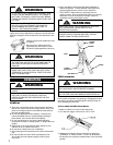
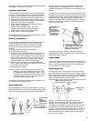
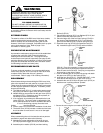
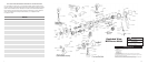
J. Assemble pawls (673-19) to pawl shafts (673-22) and
secure with snap rings (673-32). Place pawl springs
(673-21) on pawl shafts and insert these assemblies into
frame (673-2).
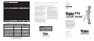
K. Slide friction hub (673-12) onto pinion (673-9) and place
one friction disc (673-13) on top of friction hub.
Assemble ratchet bushing (673-24) to ratchet (673-23).
Spring apart pawls and slide ratchet/bushing assembly
on friction hub as shown below.
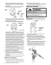
L. To assemble and adjust the brake, place the second
friction disc (673-13) on top of the ratchet. Thread the
ratchet hub (673-14) or Load Limiter (673-59) onto the
pinion (673-9). Insert the two locking pins (673-78) into
the holes of the ratchet hub or Load Limiter. Holding the
pinion steady, rotate the ratchet hub or Load Limiter from
the stop in the full clockwise position to the stop in the full
counterclockwise position. From stop to stop there
should be 10 to 45° of rotation. If the rotation does not fall
within this range, remove the locking pins, ratchet hub or
Load Limiter, pawl assemblies (see step J), friction discs,
ratchet and ratchet bushing. Slide the friction hub
partially off of the pinion until the splines disengage.
Rotate the friction hub slightly clockwise if the rotation is
more than 45° or counterclockwise if the rotation is less
than 10°. Repeat steps 1-4 until the rotation from stop to
stop is 10 to 45°. Note: The ratchet hub or Load Limiter
can be started onto the thread of the pinion in one of four
poisons. Each time the ratchet hub or Load Limiter is
threaded onto the pinion, maintain the same orientation.
Install the pawl assemblies per step K.
M. Assemble the snap ring (673-31) to the stripper pin (673-
34). Slide the stripper (673-15) into the recess in the
bottom of the frame and secure by sliding the stripper pin
thru the holes in the frame and stripper.
N. Assemble brake cover (673-8) to frame.
O. Assemble the lever assembly (step A) to ratchet hub
(673-14) or Load Limiter (673-59) and secure by
attaching the lever cover (673-17) to the ratchet hub or
Load Limiter.
P. Install load chain (673-52) - see removal and installation
of load chain.
Q. After assembly, test the unit as indicated on page 9.
REMOVAL OF LOAD CHAIN
A. Remove the lower hook block assembly from the load
chain on the 3/4 and 1-1/2 ton units. On the 3 ton unit,
disengage the load chain from the hoist hanger (673-75)
by removing the dead end pin (673-76).
B. Put unit in free-chaining - see page 2
C. Pull on the end ring (673-53) and pull the chain out of the
hoist (and out of the lower hook block on the 3 ton unit).
D. Remove the end ring from the load chain.
INSTALLING LOAD CHAIN
3/4 ton unit uses 1/4 in.(6.3mm) stock disc grade load
chain.
1-1/2 and 3 ton units use 5/16 in.(7.9mm) stock disc
grade load chain.
A. Feed a piece of soft wire thru one chain opening in the
bottom of the frame, up and over the liftwheel, until it
comes out the other opening.
B. Attach the wire to the load chain to be installed.
C. Make sure the unit is in free-chaining (see page 2).
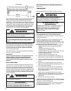
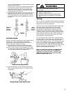
D. Position the chain so that the welds on the upstanding
links will be up and away from the liftwheel and the first
link entering the hoist is an upstanding link.
E. Pull on the wire to pull the chain up and over the
liftwheel.
F. On 3/4 and 1-1/2 ton units, attach the lower hook block to
the strand of chain that enters the “hook side” of the
frame (printed on the nameplate). Tighten the hook
block screw (673-51) firmly and then lock it in place by
prick punching two spots 180° apart on edge of
counterbore to drive metal into serrations on head of
Frame
673-2
Pawl Shaft
673-22
Pawl Snap
Ring
673-32
Pawl
673-19
Frame
673-2
Ratchet Bushing
673-24
Ratchet
673-23
Pawl Assembly
Pawl
Spring
673-21
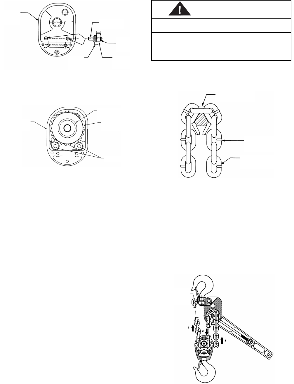
WARNING
IMPROPER INSTALLATION (REEVING) OF THE LOAD CHAIN
CAN RESULT IN A DROPPED LOAD.
TO AVOID INJURY:
• VERIFY USE OF PROPER SIZE AND TYPE OF LOAD
CHAIN FOR SPECIFIC RS2 LEVER HOIST.
• INSTALL LOAD CHAIN PROPERLY AS INDICATED BELOW
Liftwheel
673-10
Welds Out And
Away From
Liftwheel.
Load Chain
673-52
Welds Out And
Away From
Liftwheel.
Dead
End Pin
673-76