


When lubricating parts adjacent to the brake, DO NOT use
an excessive amount of lubricant which could seep onto the
brake surfaces.
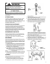
EXTERIOR FINISH
The exterior surface of the RS2 Lever Hoist has a durable,
scratch resistant baked powder coating. Normally, the
exterior surfaces can be cleaned by wiping with a cloth.
However, if the finish is damaged, compatible touch-up paint
can be purchased from Yale. Refer to page 13 for
information on ordering paint.
PREVENTATIVE MAINTENANCE
A preventative maintenance program should be established
to prolong the useful life of the hoist and maintain its
reliability and continued safe use. The program should
include frequent and periodic inspections (see page 5) with
particular attention paid to lubrication of various components
using the recommended lubricants (see Lubrication section
for lubricating load chain and other parts).
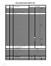
RECOMMENDED SPARE PARTS
To insure continued operation, it is recommended that two
friction discs (Key No. 673-13) be kept on hand at all times
to replace friction discs that are worn, glazed or
contaminated. Refer to page 12 for ordering information).
DISASSEMBLY
When disassembling and assembling the RS2 Lever Hoist,
refer to the exploded view and parts list on pages 10 thru 13.
These show the proper relationship of the parts, part names
and the required quantities of the parts. In addition, please
observe the following:
A. The liftwheel gear (673-11) is under spring pressure and
may spring out when the gear cover (673-5) is removed.
B. Needle bearings are pressed into the gear cover (673-5)
and frame (673-2). Unless they are to be replaced, do
not attempt to remove these bearings.
C. If so equipped, do not attempt to disassemble the Load
Limiter (673-59). The Load Limiter is calibrated by Yale,
and no attempt should be made to recalibrate the device.
If it is not functioning properly, the entire Load
Limiter must be replaced.
D. Refer to page 8 for removal and installation of load chain.
E. The brake cover (673-8) includes a rubber seal and care
should be taken to make sure it is not cut or damaged.
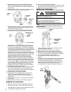
ASSEMBLY
When reassembling the unit, lubricate the various parts as
specified on page 6 and observe the following:
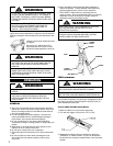
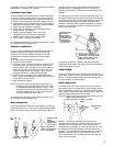
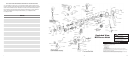
A. Maintain the proper relationship of the lever plunger
(673-46) tip and the trigger (673-43) as shown above.
B. Assemble pinion washer (673-26) and then bushing
(673-25) to pinion (673-9) and slide this assembly into
the frame (673-2).
C. Place liftwheel bearing (673-1) on liftwheel (673-10) and
slide this assembly into frame (673-2).
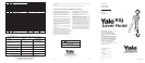
D. Place the large end of the free-chain spring (673-20) in
the recess of the liftwheel gear (673-11) and slide the
gear onto the liftwheel (673-10) spline-spring end first.
E. Assemble snap ring (673-33) to suspension bolt (673-
48). Assemble upper hook (673-35) and hook blocks
(673-16). Place this assembly in recess on top of frame
(673-2) and secure by sliding the suspension bolt thru
holes in frame and hook block. Snap ring on suspension
bolt must be on gear side of frame.
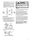
F. Push on liftwheel gear to compress the spring and attach
the gear cover (673-5) to the frame (673-2)
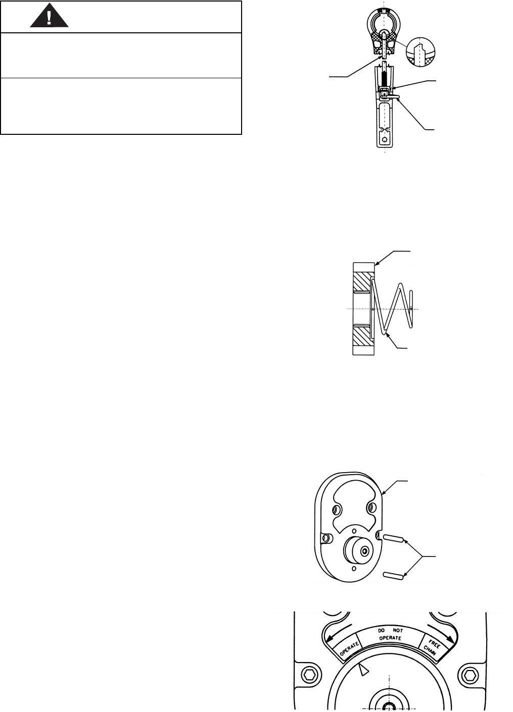
G. Insert the cam pins (673-47) - ROUND END OUT - in the
holes above and below boss on gear cover (637-5).
H. Assemble the cam (673-18) to the gear cover (673-5) so
that the arrow is pointing towards “operate”.
I. Secure the cam using the cam washer (673-60) and
screw (673-29).
Liftwheel
Gear
673-11
Trigger
673-43
Lever
Plunger
673-46
U
P
Free Chain
Spring
673-20
Cam Pins
673-47
Round End Out
Gear Cover
673-5
WARNING
USING ANY GREASE OR LUBRICANT ON THE
BRAKING SURFACES WILL CAUSE BRAKE
SLIPPAGE AND LOSS OF LOAD CONTROL WHICH
MAY RESULT IN INJURYAND/OR PROPERTY
DAMAGE.
TO AVOID INJURY:
DO NOT USE ANY GREASE OR LUBRICANT ON
BRAKING SURFACES. THE BRAKE IS DESIGNED
7