


5 Maintenance Model Ultra Trace 3000
5-6
Teledyne Analytical Instruments
5.4 System Self Diagnostic Test
1. Press the
System
button to enter the system mode.
2. Use the < > arrow keys to move to
More,
and press
Enter
.
3. Use the < > arrow keys to move to
Self-Test,
and press
Enter
.
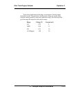
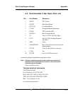
The following failure codes apply:
Table 5-1: Self Test Failure Codes
Power
0OK
1 5 V Failure
2 15 V Failure
3 Both Failed
Analog
0OK
1 DAC A (0–1 V Concentration)
2 DAC B (0–1 V Range ID)
3 Both Failed
Preamp
0OK
1 Zero too high
2 Amplifier output doesn't match test input
3 Both Failed
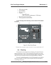
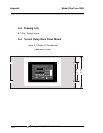
5.5 Major Internal Components
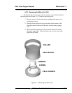
The Micro-Fuel cell is accessed by unlatching and swinging open the
front panel, as described earlier. Other internal components are accessed by
removing the rear panel and sliding out the entire chassis. See Figure 5-4,
below. The gas piping is illustrated in Figure 2-4, and the major electronic
components locations are shown in Figure 2-5, in chapter 2.
WARNING: SEE WARNINGS ON THE TITLE PAGE OF THIS
MANUAL.
The Ultra Trace 3000 contains the following major components:
• Analysis Section
Micro Fuel Cell (B-2CXL)
Cell block with stainless steel wetted parts
Sample system