


Ultra Trace Oxygen Analyzer Installation 3
3-3
Teledyne Analytical Instruments
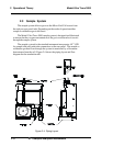
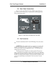
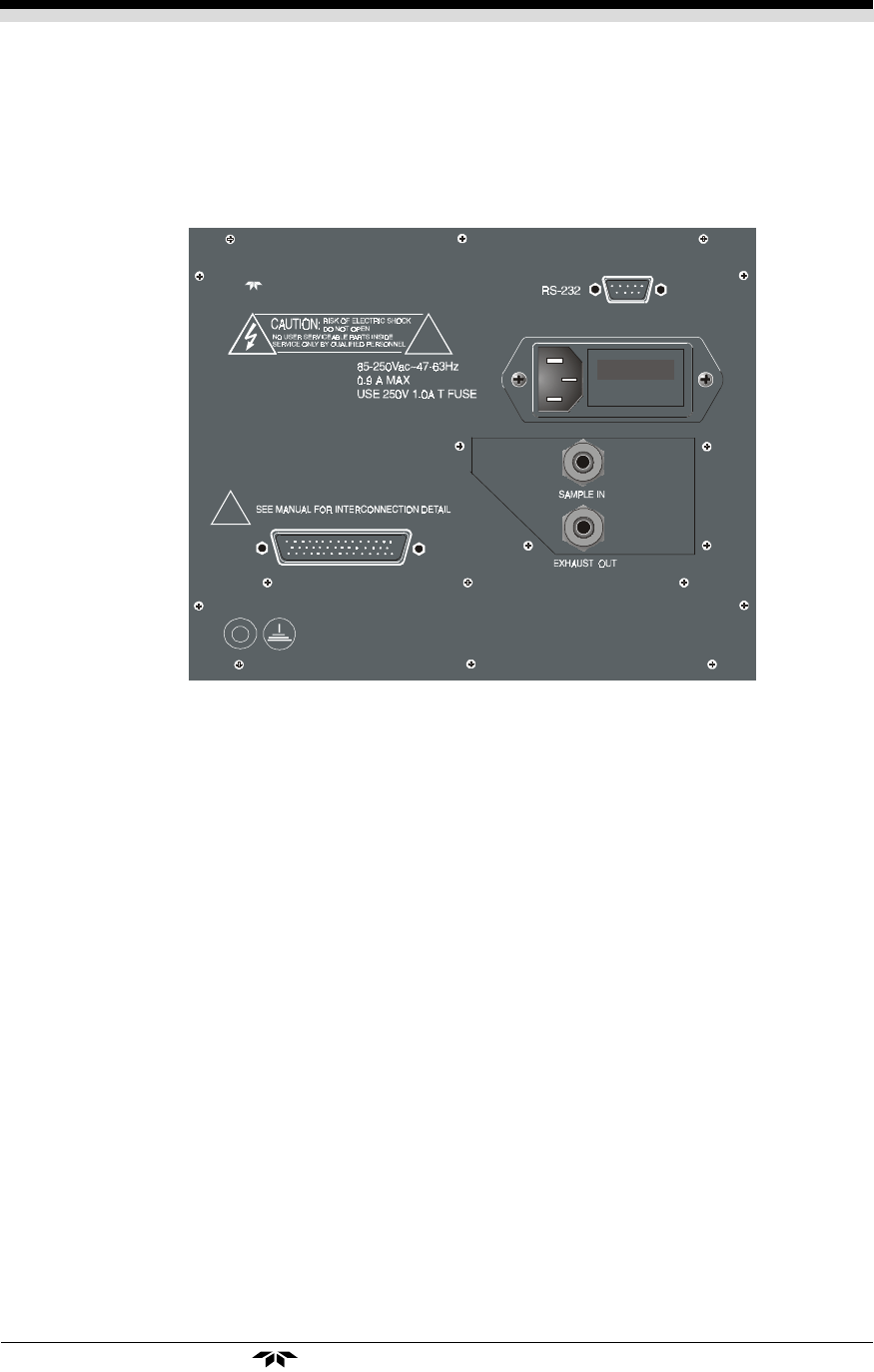
3.3 Rear Panel Connections
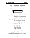
Figure 3-3 shows the Model Ultra Trace 3000 rear panel. There are
ports for gas inlet and outlet, power, communication, and both digital and
analog concentration output.
Figure 3-3: Rear Panel of the Model Ultra Trace 3000
3.3.1 Gas Connections
The unit is manufactured with
1
/4 inch VCR fittings. For a safe connec-
tion:
SAMPLE IN: In the standard model, gas connections are made at the
SAMPLE IN and EXHAUST OUT connections. Calibration gases must be
Tee'd into the Sample inlet with appropriate valves. A VCR fitting is pro-
vided for the inlet connection.
The inlet gas pressure should be reasonably regulated. Pressures be-
tween 1 and 50 psig are acceptable as long as the pressure, once established,
will keep the front panel flowmeter reading in an acceptable range (0.5 to 2.0
SLPM). For non-pressurized sample or very low pressure, (less than 1 psig)
vacuum service plumbing is recommended. (See next section: Vacuum
Service).
Teledyne Analytical Instruments