3 Operation Model OT-2 System
3-6
Teledyne Analytical Instruments
3.2 Installing the Micro-Fuel Cell
The Micro-Fuel Cell is not installed in the cell block when the
instrument is shipped. Install it before the analyzer is placed in
service.
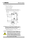
When the micro-Fuel Cell needs to be installed or replaced,
follow the procedures in chapter 5,
Maintenance,
for removing
and installing cells.
Recommendation: During installation, minimize the time the
sensor is exposed to atmospheric oxygen, i.e. the time between
removal of the sensor from the sealed bag to installation into the
cell holder.
3.3 Calibration
The calibration process consists of:
• Connecting span gas to Span In Port
• Setting the span
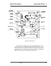
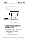
Setting the span of the transmitter requires adjustment of the
potentiometer located on the transmitter box.
The sensor will respond to changes in oxygen concentration
immediately after installation. For maximum performance (accu-
racy and sensitivity) TET/AI recommends that the sensor be purged
with a zero (0% oxygen) gas for about 24 hours after the sensor is
installed and then calibrate with span gas with a value of approx.
80-100% of the analytical range of interest. The following sections
describe the calibration procedure.
3.3.1 Calibration Gas Connections
Prior to installation of the O
2
cell, a zero gas (purge gas) con-
taining less than 1 ppm O
2
, should be connected to the system
and be ready to purge the O
2
cell. To facilitate spanning the zero
and span gas source can be connected to a common manifold
via a three way valve. This manifold then connects directly to the
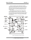
"Span Gas In" port on the system (Fig. 3-5).
It is important that the
operator bleeds any trapped air in the tubing prior to installation
of the sensor to minimize the amount of atmospheric oxygen
introduced into the system.
NOTE: In order to minimize the time required to purge the cell
after exposure to air, limit the time the cell is exposed to
air to 1 minute or less, if possible.


