


Teledyne Analytical Instruments
2-8
2 Operational Theory Model OT-2 System
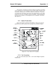
2.6 Sample System
The system consists of a shut off valve, particulate filter, pres-
sure regulator, scrubber, calibration selector valve, flow control
valve, O
2
transmitter and a sample flow meter and incorporates ¼
inch tube fittings for sample inlet and outlet connections at the
side of the enclosure.
H
2
S from the sample gas can diffuse into the Micro-Fuel Cell
leading to the formation of lead sulphide with the anode material.
To eliminate the deleterious effect of H
2
S on the sensor, the scrub-
ber is filled with Purafil
®
.
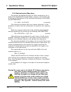
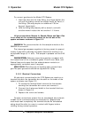
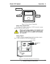
Sample Flow Description
: (See Figure 2-4)
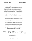
1. The sample enters the transmitter system via the shut off valve
at 6-40 psig and passes through the filter where particulates, to
90 microns, are trapped.
2. A pressure regulator, which has been preset at the factory to
approximately 5 psig ensures a constant gas flow to the sensor.
3. After the pressure regulator, the sample gas passes through the
scrubber to the calibration selector valve.
4. When the sample has been selected, it flows through the flow
control valve to the O
2
sensor.
5. Finally, the sample flows through the flow meter and exits the
system through the vent line to a safe area at atmospheric
pressure.
Note: The flow control valve should be adjusted until the
flow meter indicates a flow rate of 0.4 scfh.
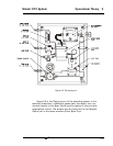
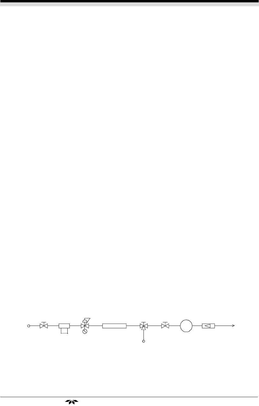
Figure 2-4 Flow Diagram
SAMPLE IN
6-40 PSIG
FILTER
H2S
SCRUBBER
SPAN GAS IN
O2 XMTR
0-10 PPM
FLOWMETER
.1-1.0 SCFH
VENT TO
ATMOSP H ERE
PRESSURE
(SAFE AREA)