


Operation LXT-220 DO
Teledyne Analytical Instruments 44
displays for them in the setup section, and they can be used for alarm
purposes or otherwise. The bottom line of the display will identify the
relay as being assigned to a PID output, and it will also show what the
input to the PID processor is assigned to.
A 0% relay setpoint refers to the minimum PID output, which
corresponds to a current of 4 mA on any current loops assigned to the
PID, and a 100% setpoint corresponds to a 20 mA current. When 4-20
mA outputs are assigned to a PID output, it is helpful to assign one of
the manual mode displays (Section 3.3.3) to one of the them so that the
percent output of the controller will be visible in the operational
displays.
See Section 3-5 Proportional Control Setup and Configuration for
configuring and setting up the optional PID control feature.
3.4 Calibration
Calibration involves performing either a one-point standardization
calibration or two-point span calibration. These choices are available
after choosing BUFFER from the Parameter Selection Menu
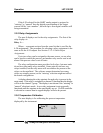
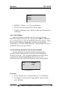
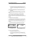
3.4.1 Manual Output Mode
In order to perform calibrations without interfering with control or
recorder functions, the LXT-220 incorporates a manual output mode. In
the manual output mode, the current output is set to the desired level and
saved until changed or released from the manual mode. On LXT-220s
with the optional PID controller output on channel 2, the current output
displayed is the PID controller output. The following procedure
demonstrates the use of the manual output.
Note: Prior to any calibration, The LXT-220 controller should be
placed into the manual mode