


Operation LXT-220 DO
Teledyne Analytical Instruments 36
cyclic. Use either of the MENU SELECT ▲/▼ keys to accept the
selection and move the cursor back to the left. The displayed selection
remains in effect until changed and the selection is remembered through
power outages of indefinite length.
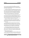
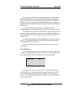
Up to two 4-20 outputs can be assigned to the same source. There is
no error indication if more than two are assigned to the same source, but
there will be no span display for the third. A span display will otherwise
be present in the main menu for each 4-20 output that is assigned to a
source. If the source is associated with channel 2 then the span display
will be in the channel 2 group. The new assignment is not functional
until the setpoints in the span display are set. If a PID controller is
selected as a source then its support displays will also be present.
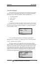
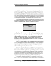
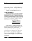
The next two displays are for the second and third 4-20mA outputs.
Some units do not have all three outputs, but the displays will show
three output options anyway, as the additional outputs can be retrofitted.
The 'missing' assignment should be selected for uninstalled outputs. The
software cannot determine how many 4-20 outputs are installed, so the
'missing' selection might not reflect the actual configuration.
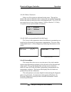
Output #4 is dedicated to HART, and its assignment is discussed in
the HART section. If the instrument is not connected to a HART
network then the fourth output can be used like any of the other outputs.
The fourth output is only present if the instrument was purchased with
the HART option.
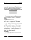
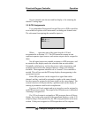
A span display will be present in the setup menu for each 4-20
output that is assigned to a source unless the source is a PID controller.
PID controllers have different setup displays, and they are in the same
section. If the source is associated with channel 2 then the display will be
in the channel 2 group. The new assignment is not usable until the
setpoints or PID parameters are specified in the operational displays.
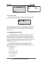
The third line of the display will show a line such as (ch1 man
mode) if an assignable manual mode control is associated with the
output. The line will begin with a question mark if making the current
selection permanent would result in a manual mode assignment conflict.
Refer to Section 3.3.3 Manual Mode Assignment for more information.
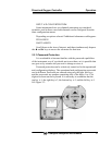
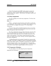
3.3.3 Manual Mode Assignment
In the manual output mode, the current output is manually set to the
desired level and saved until changed or released from the manual mode.
The main menu display shows the process value and a 4-20 mA percent