


TT
TT
T
race Oxygrace Oxyg
race Oxygrace Oxyg
race Oxyg
en Analen Anal
en Analen Anal
en Anal
yzyz
yzyz
yz
erer
erer
er
Installation 3Installation 3
Installation 3Installation 3
Installation 3
3-3
Teledyne Analytical Instruments
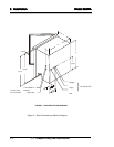
The analyzer should have a vent line of ¼" diameter tubing at least two
feet long, running
downwarddownward
downwarddownward
downward from the vent connection. This is to prevent
air from diffusing into the reservoir and dissolving into the humidifier make-
up water.
If it is not desirable to vent the sample into the atmosphere, a vent line
to carry the sample to a suitable venting area will be required. The sample
leaves the vent connection of the analyzer saturated with water vapor at a
temperature somewhat above ambient, so a suitable trap to remove conden-
sate without plugging the vent line will be required. The vent line should
also be arranged so that it cannot become plugged by dirt or dust.
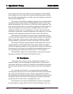
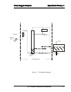
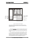
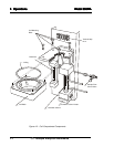
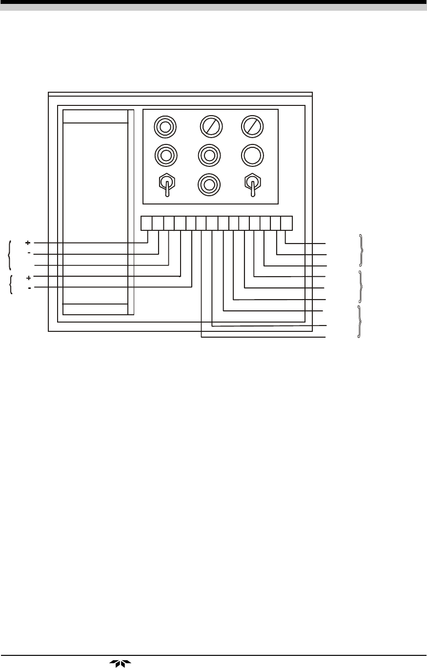
Figure 2-2: General Connection Diagram
See the specific Interconnection Diagram for your instrument in the drawing
package located at the back of the manual. See also any Addenda that may be
included with this manual.
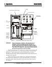
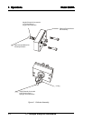
TS 1
1 2 3 4 5 6 7 8 9 10 11 12 13 14
GND
mV
Output
Current
Output
HOT
NEUT
GND
NO
C
NC
NO
C
NC
AC Power In
150 Watt Max
Load
Alarm 2
Alarm 1