TT
TT
T
race Oxygrace Oxyg
race Oxygrace Oxyg
race Oxyg
en Analen Anal
en Analen Anal
en Anal
yzyz
yzyz
yz
erer
erer
er
Installation 3Installation 3
Installation 3Installation 3
Installation 3
3-1
Teledyne Analytical Instruments
InstallationInstallation
InstallationInstallation
Installation
3.1 Location3.1 Location
3.1 Location3.1 Location
3.1 Location
With proper shielding of the leads, the analyzer and the readout device
can be separated by as much as 1,000 feet. However, they should be placed
as close together as possible. For the most convenient operation, the read-
out recorder or meter should be within view of the controls, particularly
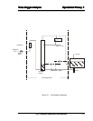
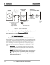
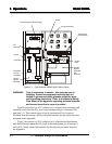
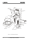
when the unit is being calibrated. Figure 2-1 depicts a typical system layout.
Other location considerations:
1) The analyzer should be sheltered from the elements.
2) Ambient temperature must be within
30 to 120 °F.30 to 120 °F.
30 to 120 °F.30 to 120 °F.
30 to 120 °F.
3) The unit should not be subject to excessive shock or vibration.
4) It should be as close as possible to the sample point.
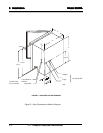
5) There must be access to the back and side of the unit for
connection or maintenance of sample lines and power.
NOTE:NOTE:
NOTE:NOTE:
NOTE:
Since the level of the electrolyte in the measuring cell is critical andSince the level of the electrolyte in the measuring cell is critical and
Since the level of the electrolyte in the measuring cell is critical andSince the level of the electrolyte in the measuring cell is critical and
Since the level of the electrolyte in the measuring cell is critical and
the water level control system for the humidifier is gravity sensitive,the water level control system for the humidifier is gravity sensitive,
the water level control system for the humidifier is gravity sensitive,the water level control system for the humidifier is gravity sensitive,
the water level control system for the humidifier is gravity sensitive,
THE ANALYZER MUST BE MOUNTED SO THAT THE BOTTOM OFTHE ANALYZER MUST BE MOUNTED SO THAT THE BOTTOM OF
THE ANALYZER MUST BE MOUNTED SO THAT THE BOTTOM OFTHE ANALYZER MUST BE MOUNTED SO THAT THE BOTTOM OF
THE ANALYZER MUST BE MOUNTED SO THAT THE BOTTOM OF
THE CASE IS LEVEL.THE CASE IS LEVEL.
THE CASE IS LEVEL.THE CASE IS LEVEL.
THE CASE IS LEVEL.
3.2 Electrical Connections3.2 Electrical Connections
3.2 Electrical Connections3.2 Electrical Connections
3.2 Electrical Connections
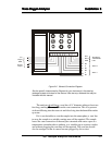
A diagram of the necessary electrical connections is shown in Figure 2-2.
Note: Note:
Note: Note:
Note:
See the Interconnection Diagram (drawing A-37526) included in theSee the Interconnection Diagram (drawing A-37526) included in the
See the Interconnection Diagram (drawing A-37526) included in theSee the Interconnection Diagram (drawing A-37526) included in the
See the Interconnection Diagram (drawing A-37526) included in the
back of this manual, as well as any Addenda that may be includedback of this manual, as well as any Addenda that may be included
back of this manual, as well as any Addenda that may be includedback of this manual, as well as any Addenda that may be included
back of this manual, as well as any Addenda that may be included
with this manual for information specific to your instrument.with this manual for information specific to your instrument.
with this manual for information specific to your instrument.with this manual for information specific to your instrument.
with this manual for information specific to your instrument.


