


Installation 3000ZA-3X
Teledyne Analytical Instruments 18
CAUTION: POWER IS APPLIED TO THE INSTRUMENT'S
CIRCUITRY AS LONG AS THE INSTRUMENT IS
CONNECTED TO THE POWER SOURCE. THE RED
SWITCH ON THE FRONT PANEL IS FOR SWITCHING
POWER ON OR OFF TO THE DISPLAYS AND
OUTPUTS ONLY.
The universal power supply requires an 85–250 VAC, 47-63 Hz
power source.
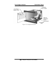
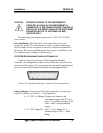
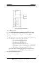
Fuse Installation: The fuse block, at the right of the power cord
receptacle, accepts US or European size fuses. A jumper replaces the
fuse in whichever fuse receptacle is not used. Fuses are not installed at
the factory. Be sure to install the proper fuse as part of installation. (See
Fuse Replacement in Chapter 5, Maintenance.)
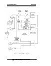
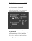
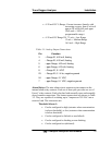
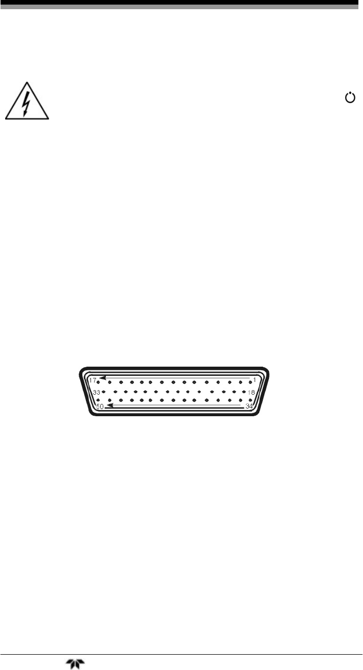
3.3.2.2 50-PIN EQUIPMENT INTERFACE CONNECTOR
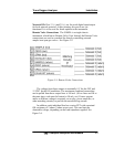
Figure 3-4 shows the pin layout of the Equipment Interface
Connector. The arrangement is shown as seen when the viewer faces the
rear panel of the analyzer. The pin numbers for each input/output function
are given where each function is described in the paragraphs below.
Figure 3-4: Equipment Interface Connector Pin Arrangement
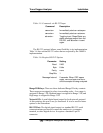
Analog Outputs: There are four DC output signal pins—two pins per
output. For polarity, see Table 3-1. The outputs are:
0–1 VDC % of Range:Voltage rises linearly with
increasing oxygen, from 0 V at 0
ppm to 1 V at full scale ppm. (Full
scale = 100% of programmable
range.)
0–1 VDC Range ID: 0.20 V = Low Range, 0.5 V =
Medium Range, 0.80 V = High
Range.