


Trace Oxygen Analyzer Installation
Teledyne Analytical Instruments 21
• Actuates when DC power supplied to circuits is
unacceptable in one or more parameters. Permanently
configured as failsafe and latching. Cannot be defeated.
Actuates if self test fails.
• (Reset by pressing button to remove power. Then
press again and any other button EXCEPT System to
resume.
• Further detail can be found in Chapter 4, Section 4-5.
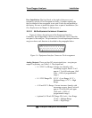
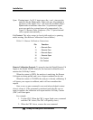
Table 3-2: Alarm Relay Contact Pins
Pin Contact
45 Threshold Alarm 1, normally closed contact
28 Threshold Alarm 1, moving contact
46 Threshold Alarm 1, normally open contact
42 Threshold Alarm 2, normally closed contact
44 Threshold Alarm 2, moving contact
43 Threshold Alarm 2, normally open contact
36 System Alarm, normally closed contact
20 System Alarm, moving contact
37 System Alarm, normally open contact
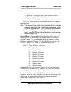
Digital Remote Cal Inputs: Accept 0 V (off) or 24 VDC (on) inputs for
remote control of calibration. (See Remote Calibration Protocol below.)
See Table 3-3 for pin connections.
Zero: Floating input. 5 to 24 V input across the + and – pins puts the
analyzer into the Zero mode. Either side may be grounded at
the source of the signal. 0 to 1 volt across the terminals allows
Zero mode to terminate when done. A synchronous signal must
open and close the external zero valve appropriately. See
Remote Probe Connector. (The –C option internal valves
operate automatically.)