Operating Basics
P7240 4 GHz 5X Active Probe User Manual
19
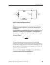
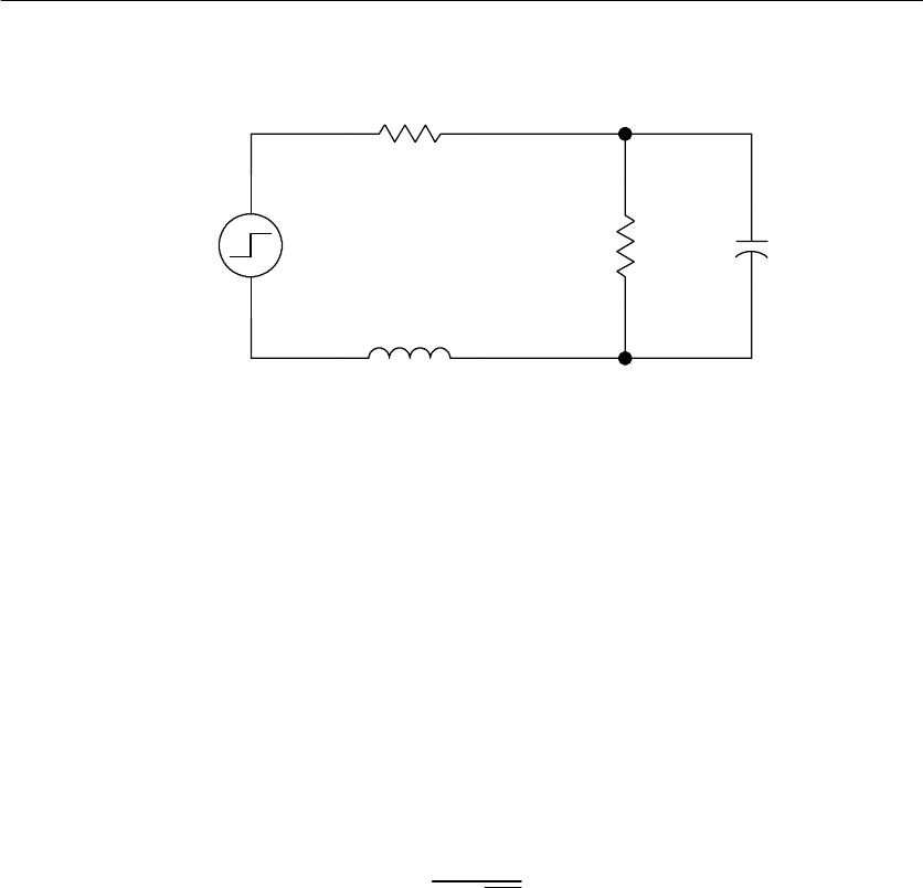
R
source
V
source
Probe C
in
0.85 pF
Probe R
in
20 kΩ
L
gl
(Ground Lead)
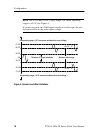
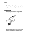
Figure 6: Ground Lead Equivalent Circuit
Ringing and rise time degradation can be masked if the frequency
content of the signal degradation is beyond the bandwidth of the
oscilloscope.
You ca n determine if ground lead effects may be a problem in your
application if you know the self-inductance (L) and capacitance (C)
of your probe and ground lead. Calculate the approximate resonant
frequency (f
0
) at which this parasitic circuit will resonate with the
following formula:
f
0
=
1
2π LC
Ꭹ
The preceding equation shows that reducing the ground lead
inductance will raise the resonant frequency. If your measurements
are affected by ringing, your goal is to lower the induct ance of your
ground path until the resulting resonant frequency is well above the
frequency of your me asurements.
The low-inductance ground contacts described in Features and
Accessories starting on page 5 can help you reduce the effects of
ground lead inductance on your measurements.


