


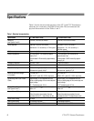
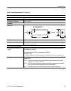


Operation
CT-1/CT-2 Current Transformer
7
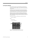
Low Frequency Response
The low-frequency response of the current transformer is proportional to the
inductance of the transformer windings. A DC component in the current being
measured tends to reduce this inductance. Figures 2 and 3 show this effect in the
frequency domain.
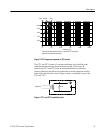
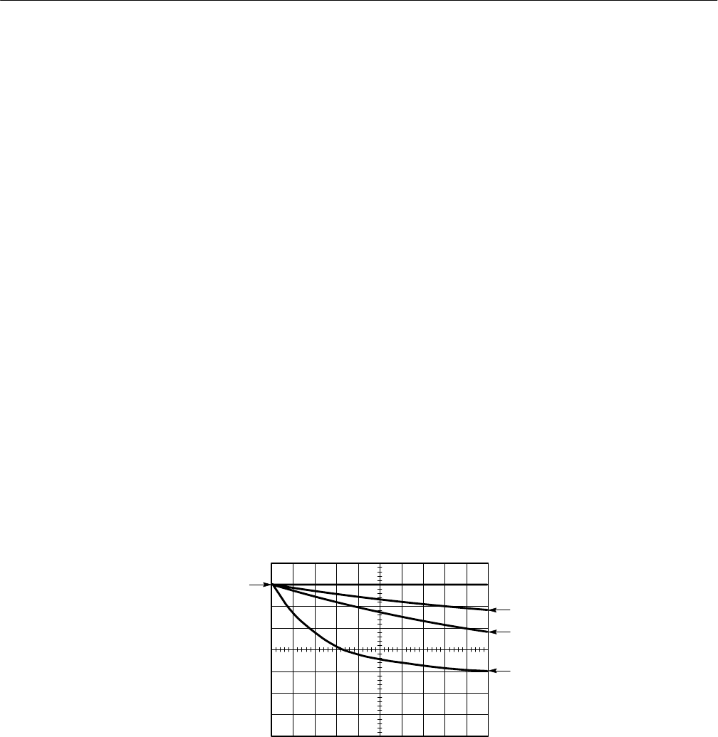
This effect is also seen in the time domain. Figure 6 shows that the pulse tilt is
increased in the presence of significant DC current. The DC current required to
increase the tilt by a factor of two is about 0.3 A. Pulse currents that start at zero
and remain unidirectional have a DC component that the user should consider.
When droop is present at low frequencies, the apparent overall peak-to-peak
height from top to bottom is not the true current. The height of a flat-top pulse
still can be measured accurately by observing the transition edge of the pulse. In
Figure 7, the 50 mA pulse is faithfully reproduced at the high-to-low transition at
the center of the screen.
Pulse width, tilt, and the lower 3 dB frequency are related by the formula:
Percent tilt = 200π Tp f
1
Where:
Tp = pulse width
f
1
= lower 3 dB frequency
Input
current
Output
voltage
0.3 A
DC
1 A
DC
0 A
DC
20 ms/div10 mA/div
Figure 6: CT-1 decay characteristics referenced to front corner