


6
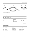
CT-1/CT-2 Current Transformer
Operation
This section describes how to install the CT-1 or CT-2, discusses low-frequency
probing, and provides information on safety and product care.
Installing the CT-1 or CT-2
The CT-1 or CT-2 transformers can be attached to the chassis or circuit board to
measure current in transistors, diodes, or other components. Any number of
transformers can be used.
When observing the output of a CT-1 or CT-2 transformer, ensure it is terminated
into 50 W. If the oscilloscope input is not 50 W, use a suitable matching
terminator (see recommended accessories in the Replaceable Parts List).
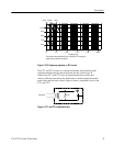
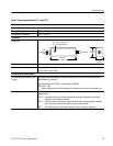
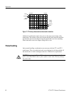
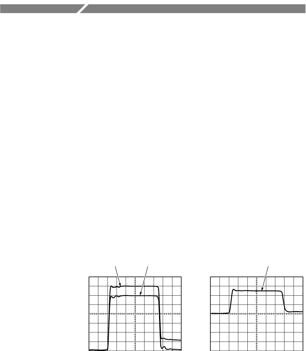
Figure 5 shows the output of the CT-1 compared with the input pulse from a
250 ps fast-rise pulse generator and the output of the CT-2 as seen by a 100 MHz
oscilloscope system.
If the CT-1 or CT-2 is connected so that the positive (+) label side faces the
signal source, the input current and output voltage will be in phase. This is the
preferred connection. For pulses with a risetime slower than 1 ns, the CT-1 or
CT-2 may be connected in either polarity.
Ground and the voltage ratings do not apply when installed on a fully insulated
conductor. The 175 V rating is based on long term applications that may degrade
the insulation. The voltage on bare signal wire must be limited to the 175 V
RMS
and the 1000 V DC + peak AC ratings.
2 ns/div100 mV/div
CT-1 output waveform
20 ns/div
CT-2 output waveform
100 mV/div
Input current Output voltage
Output voltage
Figure 5: CT-1 and CT-2 output waveform