


930487 Rev. A
IX. Set-Up & Adjustment
35
IX. Set-Up & Adjustment
930487 Rev. A
34
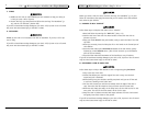
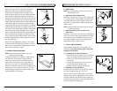
K. WHEEL LOCKS
NOTE– Use a torque setting of 100 in.-lbs when set-
ting-up wheel locks.
1. High-Mount Scissor Wheel Locks:
Loosen the screws (A) on the top of each clamp using
a 3/16 Allen wrench. Slide assembly toward rear wheel
until clamp embeds into tire to prevent wheel move-
ment when in locked position. Adjust angle position.
Tighten screws.
NOTE– Clamp and wheel lock may need to be rotated
to clear frame tubing.
2. High-Mount Push-to-Lock or Pull-to-Lock
Wheel Locks
Loosen the screws (B) on the top of each clamp using a
3/16" Allen wrench. Slide clamp toward the rear wheel
until the wheel lock is embedded into the tire to pre-
vent wheel movement, when in the locked position.
Adjust angle position. Tighten screws.
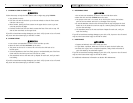
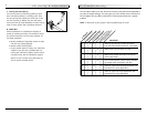
L. ANTI-TIP TUBES (OPTIONAL)
Sunrise Medical recommends anti-tip tubes for all
wheelchairs. Use torque setting of 88 in.-lbs. when
installing anti-tip tubes.
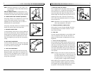
1. Inserting Anti-tip Tubes Into Receiver
a. Press the rear anti-tip release lever on the anti-tip
tube so that both release pins are drawn inside.
b. Insert the anti-tip tube (C) into the anti-tip
receiver (D).
c. Turn the anti-tip tube down until release pin is
through the receiver mounting hole.
d. Insert second anti-tip tube the same way.
2. Adjusting Anti-Tip Tube Wheel
The anti-tip wheels may have to be raised or lowered
to achieve proper clearance of 1 1/2" to 2".
Press the anti-tip wheel release button so that both
release pins are drawn inside. Raise or lower to one of
the three predrilled holes. Release button. Adjust the
second anti-tip tube wheel the same way. Both wheels
should be exactly the same height.
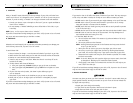
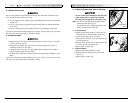
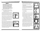
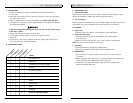
Loosen the stem bolt (A) on the right fork using an
8mm Allen wrench. Do not remove the stem bolt.
Simply loosen it enough to allow the teeth on the
upper and lower splines to clear one another (B). With
the stem bolt loosened, the caster fork should pivot
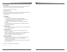
freely. Place the wheelchair on the floor so that the two
rear wheels and left caster contact the floor. Place some
weight in the seat towards the rear to help stabilize the
chair. Place a square or pocket level against the flat
surface of the fork and pivot the fork until it is vertical
(square). With the fork vertical, engage the teeth of the
two splines to the closest mating position. Make certain
that the teeth are properly engaged and not crossed.
Shine a bright light behind the mating spline teeth and
check for proper teeth engagement. Tighten the stem
bolt to secure the spline mating position. The stem bolt
should be tightened to 20 ft-lbs to ensure that it does
not loosen during use.
Record the teeth engagement position of the splines
on the right fork, and adjust the left fork in a similar
fashion to the same position. Reassemble both casters,
and re-check that they are square.
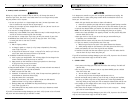
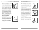
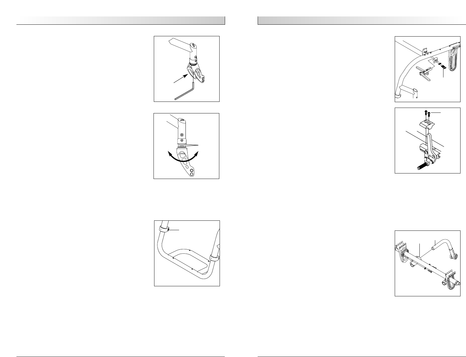
J. FOOTREST HEIGHT ADJUSTMENT
NOTE– Use a torque setting of 100 in.-lbs. when
adjusting footrest height.
To adjust the height of your footrest, loosen the two
cap screws (C) on the footrest clamps. Slide the
footrest up or down to the new desired height and
tighten the two cap screws. Use a torque setting of
100 in-lbs (11.3 N-m). It is recommended that you
maintain a minimum of 2.0 inches (5 cm) between the
lowest point on the footrest and the floor. This will
provide adequate clearance for uneven surfaces and
prevent damage to your footrest.
C
A
B
D
C
A
B