


930487 Rev. A
IX. Set-Up & Adjustment
31
Once the axle and back plates are secured, attach the
rear wheels, occupy the chair and maneuver it with a
spotter to get a feel for the new adjustment.
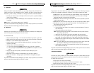
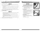
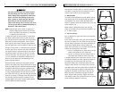
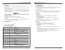
2. Wheel Camber
The wheel camber adjustment provides greater side-to-
side stability due to the increased width and angle of
the wheelbase. The wheel camber adjustment also
allows for quicker turning and greater access to the top
of the handrims. (A)
Wheel camber is determined by the axle tube (B).
Tubes are available from your authorized supplier in 0º,
2°, 4º and 8º angles.
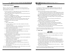
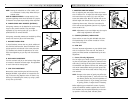
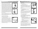
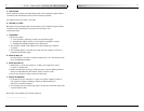
3. Toe-in or toe-out
Prior to adjusting for toe-in/out follow the instructions
of section H-4.
Toe-in and Toe-out refers to how well the rear wheels of
the chair are aligned. This will affect how well the chair
will roll. Drag or resistance occurs when the wheels are
not properly aligned. Remove the rear wheels and
loosen the 8 cap screws (C) (4 per side) that secure the
camber tube. Re-attach the rear wheels.
a. Toe-in: To eliminate toe-in, rotate the top of the
camber tube toward the rear of the chair.
b. Toe-out: to eliminate toe-out, rotate the top of
the camber tube toward the front of the chair.
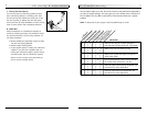
A properly adjusted chair should have no toe-in or toe-
out. Measure between the outer edge of the wheels on
the leading (E) and trailing (D) sides of the tire.
Rotate the camber tube as described above until the
wheel-to-wheel distance is the same at the front and
rear. Make certain that the camber tube is centered left
to right by measuring the length of tube extending
beyond the axle plate on both sides of the chair (F).
When the tube is centered these lengths should be
equal. Tighten the 8 cap screws. Tighten the screws
concurrently to 88 in-lbs. Pre-check for toe-in/out and
proper centering. Readjust if necessary.
IX. Set-Up & Adjustment
930487 Rev. A
30
The more you move your rear wheels forward,
the more likely your chair will tip over back-
wards. Always make adjustment in small incre-
ments, and check the stability of your chair
with a spotter to prevent tip-over. We recom-
mend that you use anti-tip tubes until you
adapt to the change and are sure you are not at
risk to tip over. Refer to additional Warnings in
Section VI “Falls and Tip Over”.
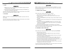
NOTE– Adjusting your chair’s center of gravity will
require re-adjusting the location of the wheel
locks (if provided). See Letter K for instructions
on adjusting the wheel locks.
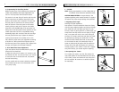
To adjust the center of gravity location, remove both
rear wheels. Remove the 4 bolts (A) and nuts (B) (2
per side) that secure the axle plates to the seat tubes.
Note that for certain configurations, some of these
bolts may also pass through the back plates. Remove
any back plate bolts, nuts and saddles if they also pass
through the axle plate, or if they obstruct the position
to which you wish to move the axle plate. Slide both
axle plates forward or rearward along the seat tube to
the desired position, and align the holes in the seat
tube and axle plate. The hole pattern allows for 1/2"
(1.3 cm) increments of adjustment. Different sets of
holes in the axle plates are used depending on the
center of gravity position.
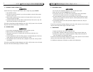
Reinstall the bolts securing the axle plates and back
plates to the camber tube. Install with shorter or longer
bolts and saddles from the additional hardware package,
as required. Bolts should occupy the outermost avail-
able holes in the axle plate. Make certain that a saddle
is always installed beneath the back plate and nut on
the inside of the chair (C) when the axle plate and back
plate do not overlap. If the edge of the axle plate over-
laps the back plate and prevents installation of the
standard saddle, then install a partial saddle supplied
with the additional hardware package.
A
B
C
A
B
C
Toe-out
Toe-in
D
E
F