


930487 Rev. A
IX. Set-Up & Adjustment
29
IX. Set-Up & Adjustment
930487 Rev. A
28
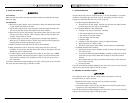
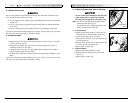
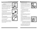
F. ADJUSTING REAR SEAT HEIGHT
Prior to adjusting rear seat height, follow the instruc-
tions in Section H-4. To adjust rear seat height, loosen
and remove the 8 cap screws (A) (4 per side) that
secure the camber tube. Move the camber tube to the
desired height and reinstall the 8 cap screws. Prior to
tightening these screws, follow the instructions for
toe-in and toe-out adjustment (Section H-3). Tighten
screws to 88 in-lbs.
NOTE– Adjustment to rear seat height may also require
caster angle adjustment. See Letter I.
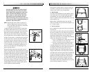
G. CUSHION (OPTIONAL) INSTALLATION
Place cushion on seat sling with VELCRO® side down.
The beveled edge of the cushion should be in front.
Press firmly into place.
H. REAR AXLE
The most important adjustment on your Quickie wheel-
chair is the position of the rear axle. The center of
gravity and wheel camber are determined by the axle
adjustment.
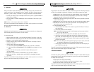
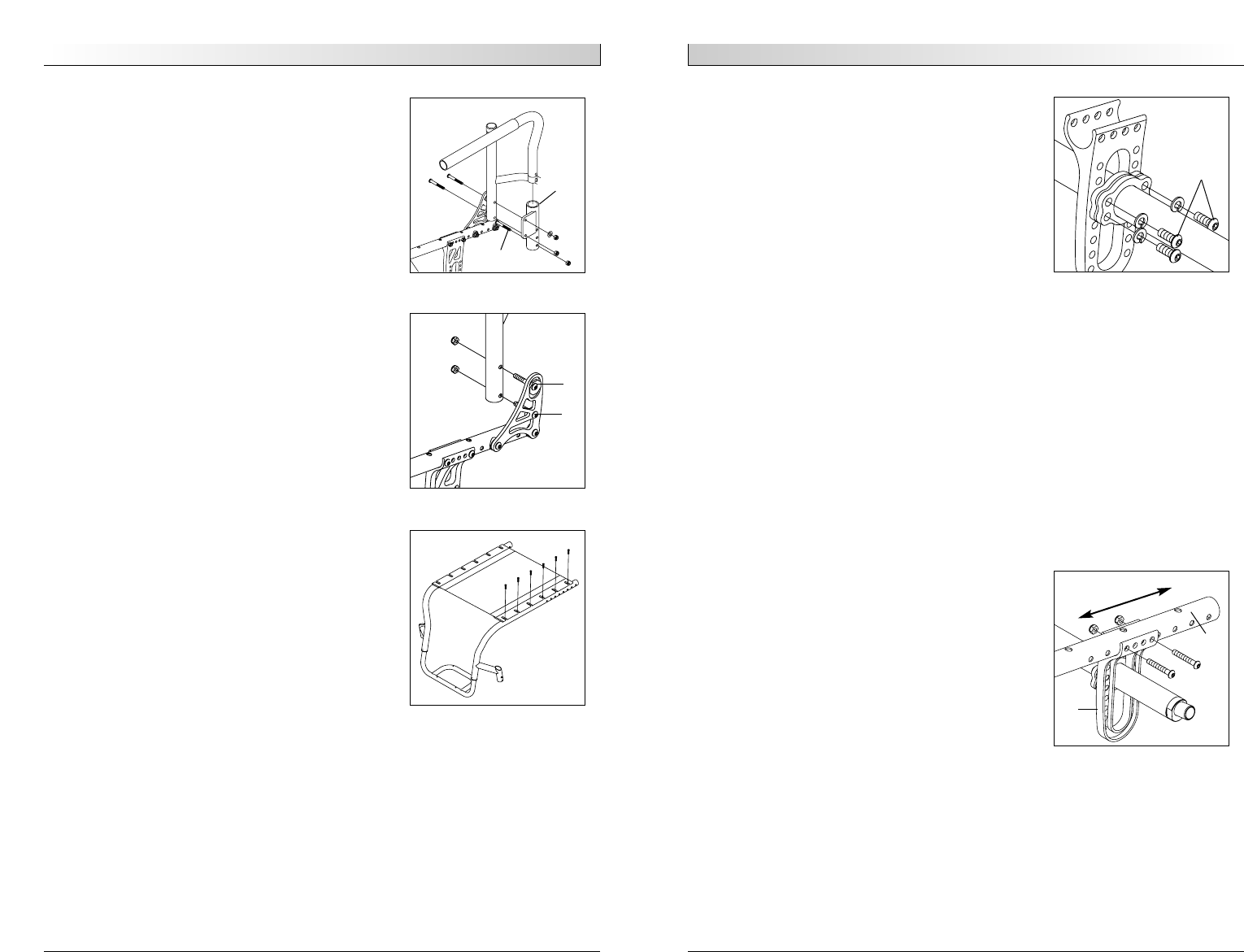
1. Center of Gravity Adjustment
You can adjust your center of gravity position by mov-
ing the two axle plates (B) forward or rearward on the
seat tube (C). Moving the axle plates forward shortens
the wheelbase and lightens the front end, making your
chair more maneuverable. Moving the axle plates rear-
ward makes the chair more stable and less likely to tip
over rearward.
NOTE– Changes to the center of gravity may affect the
rear seat height (Letter F), toe-in/toe-out of the
rear wheels (Section H-3) and the squareness of
the casters (Letter I). If you change your center
of gravity position, re-adjust these if necessary.
Before adjusting your wheelchair’s center of gravity,
locate the additional saddles supplied with the chair.
This hardware may be required depending on the over-
lap position of the axle plates and back plates.
NOTE– Setting the wheelchair on a flat surface, such
as a workbench or table, helps make these pro-
cedures easier.
NOTE ON TORQUE SETTINGS– A torque setting is the
optimum tightening which should be made on a particu-
lar fastener. Use proper torque settings where sepcified.
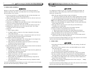
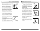
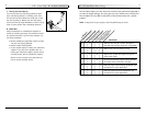
B. PADDED SWING-AWAY ARMRESTS (OPTIONAL)
Swing-away armrests can be detached or can be swung
away to allow lateral transfers. They are height
adjustable (2") by moving bolts (A) up or down in
predrilled holes on armrest bracket.
Swing-away, removable armrests are installed by sliding
armrest into receiver (B) on rear frame tubes.
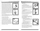
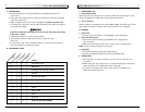
C. BACKREST INSTALLATION
To install backrest, remove the nut, plastic saddle and
bolt from the backrest tube. Place the backrest in the
upright position and reinstall in the lower plate hole
(C). Backrest bolts should be tightened to 35 in-lbs.
Avoid over-tightening as you may crush the backrest
tubing.
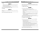
D. BACK ANGLE ADJUSTMENT
Turn the eccentric bolt (D) on the backrest hinge plate
to increase or decrease the back angle. The adjustment
on each side must be exactly equal.
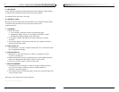
E. SEAT SLING ADJUSTMENT
Remove the screws retaining the left side seat sling.
Readjust VELCRO® -style material to increase the ten-
sion in the seat sling. Replace screws. If there is any
difficulty in reattaching the screws, try using a probe
to help line up the holes.
A
A
B
C
D
B
C