


930398 Rev. B
X. Set-Up & Adjustment
31
c. Adjust angle position.
d. Tighten screws.
2. High-Mount Push-to-Lock or Pull-to-Lock
Wheel Locks:
a. Loosen the screws on the top of
each clamp.
b. Using a 3/16" Allen wrench, turn one of the
screws counterclockwise one-quarter turn.
c. Repeat the same process with the second of the
two screws.
d Alternately loosen the screws (two turns each)
until both screws are removed.
e Slide clamp toward the rear wheel until the
wheel lock is embedded into the tire to prevent
wheel movement, when in the locked position.
f. Tighten screws.
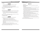
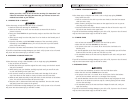
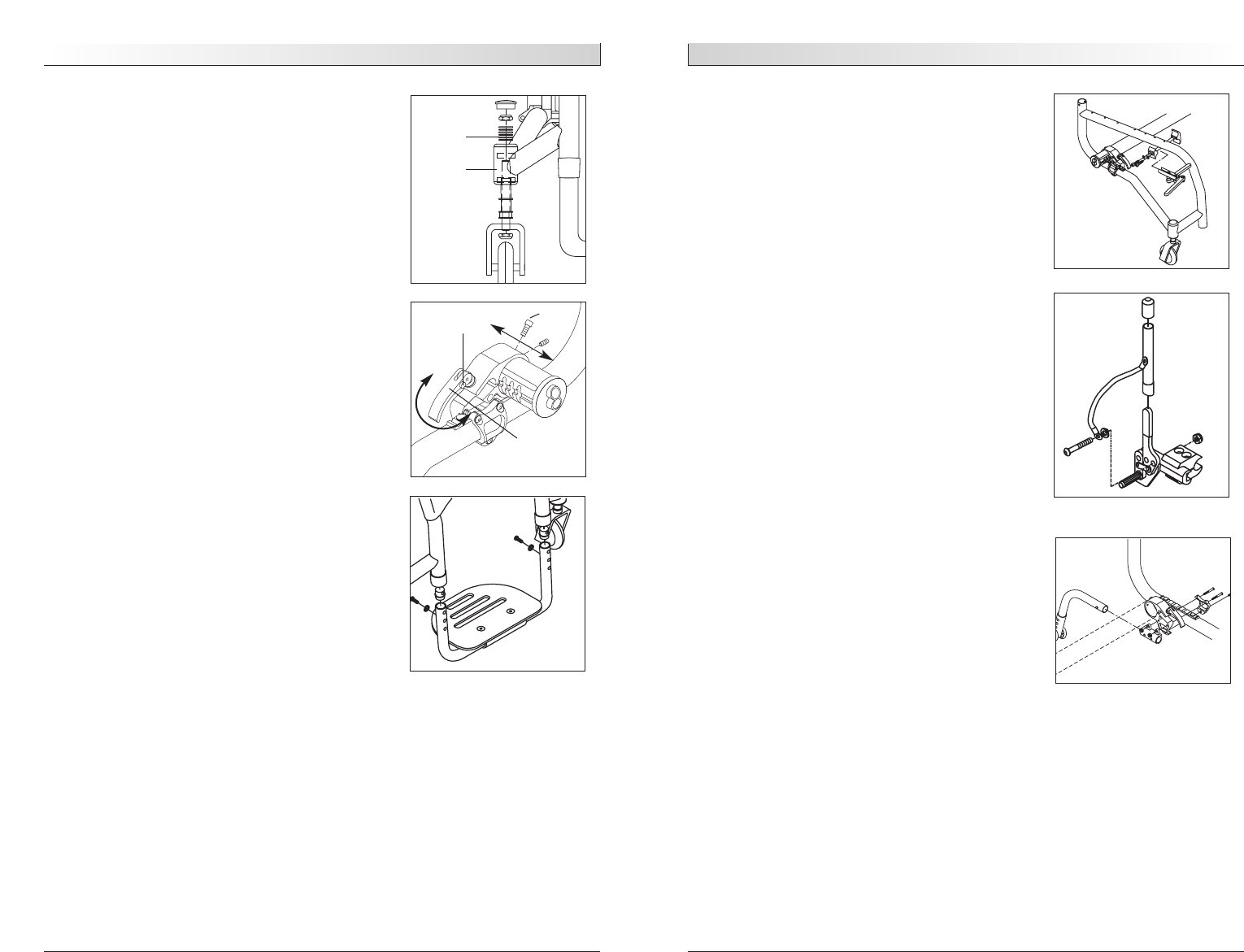
I. ANTI-TIP TUBES (OPTIONAL)
Sunrise recommends anti-tip tubes for all wheelchairs.
Use a torque setting of 100 in.-lbs. (11.3 N.m) when
setting up the anti-tip tubes.
1. Inserting Anti-Tip Tubes Into Receiver
a. Press the rear anti-tip release lever on the anti-tip
tube so that both release pins are drawn inside.
b. Insert into the anti-tip tube receiver.
c. Turn the anti-tip tube down until release pin is
through the receiver mounting hole.
d. Insert second anti-tip tube the same way.
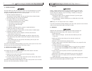
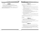
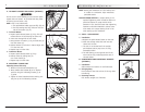
2. Adjusting Anti-Tip Tube Wheel
The anti-tip tube wheels may have to be raised or
lowered to achieve proper clearance 1 1/2" to 2"
(38 to 50 mm).
a. Press the anti-tip wheel release
button so that both release pins
are drawn inside.
b. Raise or lower to one of the three predrilled holes.
c. Release button.
d. Adjust the second anti-tip tube wheel the
same way. Both wheels should be at exactly
the same height.
X. Set-Up & Adjustment
930398 Rev. B
30
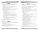
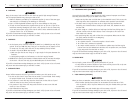
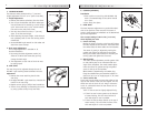
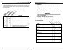
4. Wheelbase Width Adjustment
Adjusting the wheelbase width allows the rider the
option to move the wheels closer or further away
from the hips. It also compensates for camber
adjustment and gives the proper wheel spacing to
maximize pushing efficiency.
a. Press release pin to unlock lever.
b. Loosen clamp by turning locking lever counter-
clockwise.
c. Pull camber plug in or out adjusting for desired
width. Use indicating notches as a guide for
equal adjustment on both sides.
d. When desired width adjustments are made tighten
locking lever by turning clockwise. Make sure the
camber plug is equally adjusted on both sides.
e. Push down on lever until release pin locks in
position.
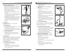
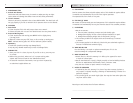
G. FOOTREST
Use a torque of 100 in.-lbs. (11.3 N.m) when
adjusting footplate.
1. Height Adjustment
a. Remove footrest tubes and slide plug up or down
inside tube to correct position.
b.The end of the plug is tapped so a screw may be
used to help position the plug at the correct hole.
2. Footplate Angle Adjustment
a. Loosen flathead screws.
b. Reposition footplate to desired angle and
retighten screws. Use a torque setting of 100
in.lb. (11.3 N.m).
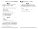
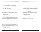
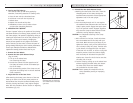
H. WHEEL LOCKS
Quickie R2 wheelchairs are shipped with one of two types
of high-mount wheel locks. Wheel locks are installed at
the factory unless you have requested otherwise.
Use a torque setting of 100 in.-lbs. (11.3 N.m) when
setting up wheel locks.
1. High-Mount Scissor Wheel Locks:
a. Loosen the screws on the top of
each clamp.
b. Slide assembly toward rear wheel until clamp
embeds into tire to prevent wheel movement,
when in locked position.
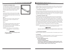
Caster
Housing
Spacers
Socket
Screw
Release
Pin
Locking
Lever