102841 Rev. A
17
ENGLISH
IX.
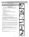
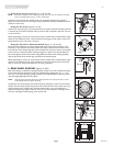
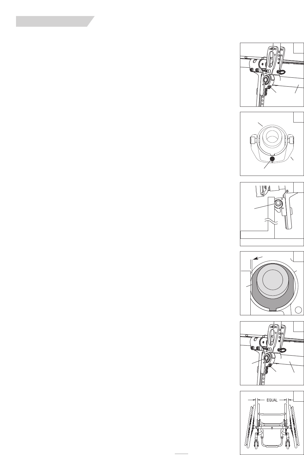
3. Setting Toe-in toe-out to zero (Figures 17, 18, 19 & 20)
NOTE– A wheelchair equipped with 0° camber plugs cannot have a toe-in toe-out condition. This adjust-
ment is only required when using 3°, 6° and 9° camber plugs.
Toe refers to how well the rear wheels of the chair are aligned relative to the ground. It
affects how well the chair will roll. Drag or rolling resistance is optimally minimized when the
wheel toe is set to zero.
Setting the T
oe to Zero
(Figures 17 & 18)
Loosen the 2 cap screws (A) (1 per side) that secure the camber tube clamp. Observe the ball
in the level (B), and rotate the camber tube (C) until the ball is centered in the level. The toe
is now set at zero.
Before tightening the screws (A), make certain that the camber tube is centered left-to-right
relative to the wheelchair frame. There should be an equal gap on both sides or none at all.
Torque fasteners (A) to 144 in-lbs. (16.3 Nm).
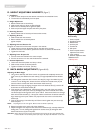
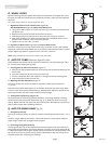
Setting the Toe to Zero– Alternative Method (Figures 17, 18, 19 & 20)
Place the entire wheelchair on a flat horizontal table or ground surface. Loosen the 2 cap
screws (A) (1 per side) that secure the camber tube clamp. Locate the flat surfaces on the
front and rear of the camber plugs (D). Place an object that is known to have an accurate 90°
corner (such as a carpenters square, drafting triangle, etc.) down on the flat horizontal sur-
face and up against the flat of the camber plug. Rotate the camber tube and plug assembly
until the flat surface of the camber plug is parallel to the measuring tool.
Before tightening the screws (A), make certain that the camber tube is centered left-to-right
relative to the wheelchair frame. There should be an equal gap on both sides of the wheel-
chair or none at all. Torque the fasteners to 144 in-lbs. (16.3 Nm).
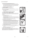
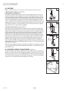
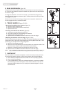
L. REAR WHEEL SPACING (Figures 21 & 22)
Rear wheel spacing is measured as the gap between the top of the rear wheels and the back-
canes, and is shown as dimension X (Fig. 22). Available factory settings are 3/4", 1", 1-1/2"
and 1-3/4". The widest setting is typically required to provide adequate tire clearance when
using the Height Adjustable Armrest option.
NOTE– When setting the rear wheel spacing only make adjustments to one side of the chair at a time.
Loosening both sides will undo the toe setting.
To adjust the rear wheel spacing, the camber inserts (E) telescope in and out of the camber
tube (F) with hard stops at each end of travel. On the left side of the chair, loosen screw (G)
(the one closest to the camber tube). Slide the camber insert in or out to establish the
required wheel spacing. Tighten screw to 144 in-lbs. (16.3 Nm). Repeat on the right side of
the chair, matching the wheel spacing set on the left side.
21
22
G
F
E
X
17
18
C
C
A
B
ball
19
20
D
D
C
parallel


