


050105 Rev. C
26
English
IX. Set-Up & Adjustment
28
G
I
29
H
A
26
C
D
B
E
F
27
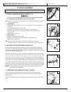
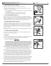
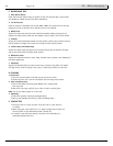
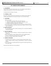
M. FOOTREST HEIGHT ADJUSTMENT (FIGURE 24)
To adjust the height of your footrest, loosen the screw (D) on both footrest clamps. Slide
the footrest up or down to the new desired height and tighten the two set screws. Use a
torque setting of 144 in-lbs (16.3 Nm). It is recommended that you maintain a minimum of
2.0 inches (5 cm) between the lowest point on the footrest and the floor. This will provide
adequate clearance for uneven surfaces and prevent damage to your footrest.
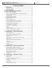
N. WHEEL LOCKS
NOTE– Use a torque setting of 100 in-lbs. (11.3 Nm) when setting-up wheel locks.
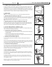
1. High-Mount Ergo Scissor Wheel Locks (Figure 25)
Loosen the screws (E) on the top of each clamp using a T30 Torx key. Slide assembly toward
rear wheel until clamp embeds into tire to prevent wheel movement when in locked posi-
tion. Adjust angle position. Tighten screws.
NOTE– Clamp and wheel lock may need to be rotated to clear frame tubing.
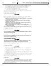
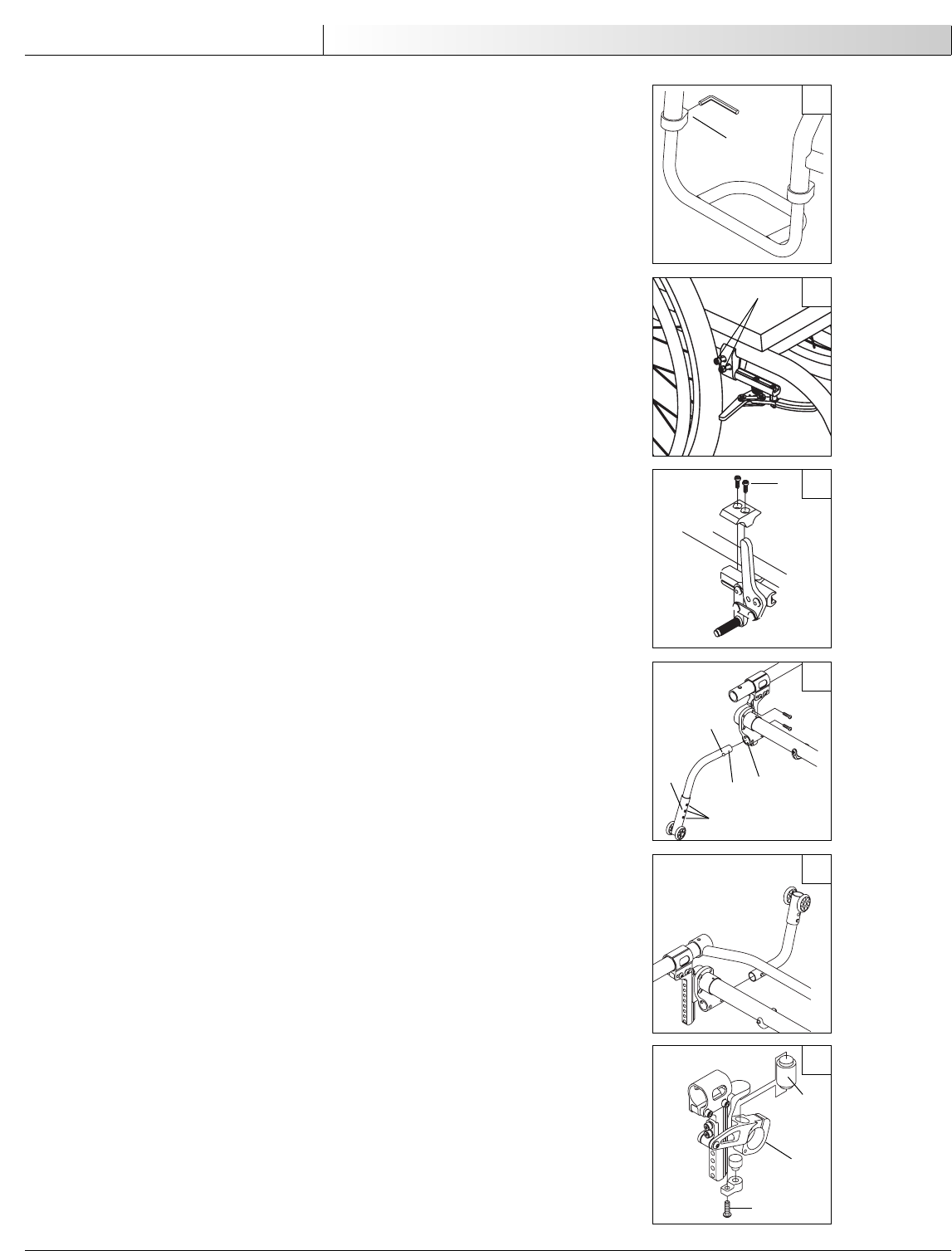
2. High-Mount Push-to-Lock or Pull-to-Lock Wheel Locks (Figure 26)
Loosen the screws (A) on the top of each clamp using a T30 Torx key. Slide clamp toward
the rear wheel until the wheel lock is embedded 1/8" into the tire to prevent wheel move-
ment, when in the locked position. Adjust angle position. Tighten screws.
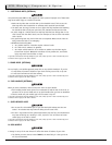
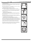
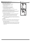
O. ANTI-TIP TUBES (OPTIONAL) (FIGURES 27 & 28)
Sunrise Medical recommends anti-tip tubes for all wheelchairs. Use torque setting of 106
in-lbs. (12 Nm) when installing anti-tip tubes.
1. Inserting Anti-tip Tubes Into Receiver (Figure 27)
a. Press the rear anti-tip release button (B) on the anti-tip tube so that both release pins
are drawn inside.
b. Insert the anti-tip tube (C) into the anti-tip receiver (D).
c. Turn the anti-tip tube down until release pin is through the receiver mounting hole.
d. Insert second anti-tip tube the same way.
2. Adjusting Anti-Tip Tube Wheel (Figure 27)
The anti-tip wheels may have to be raised or lowered to achieve proper clearance of
1 1/2" to 2".
Press the anti-tip wheel release button (E) so that both release pins are drawn inside. Raise
or lower to one of the three predrilled holes (F). Release button. Adjust the second anti-tip
tube wheel the same way. Both wheels should be the same height.
3. Turning Anti-Tip Tubes Up (Figure 28)
Turn anti-tip tubes up when being pushed by attendant, overcoming obstacles or climbing
curbs. Press the rear anti-tip tube release lever (Fig. 27-I). Hold lever in and turn anti-tip
tube up. Release the lever and repeat with second anti-tip tube. Remember to return anti-
tip tubes to down position after completing maneuver.
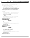
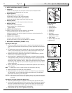
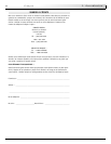
P. REAR SUSPENSION (FIGURE 29)
The performance of your suspension system is determined by the compression elastomers
(G). There are several different elastomers available from Quickie which are selected based
on the user’s weight.
To change out elastomers, remove the 2 screws (H) (1 per side). Rotate swingarms (I)
downward and the compression elastomer (G) can be freely removed from its top and bot-
tom engagement sockets.
Reverse the order to install new bushings, making sure the compression elastomers are
securely engaged into the top and bottom sockets.
24
D
E
25