


050105 Rev. C
24
English
IX. Set-Up & Adjustment
14
15
C
C
A
B
ball
16
17
D
D
C
parallel
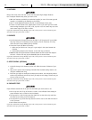
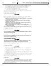
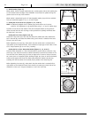
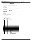
2. Wheel Camber (Figure 13)
Wheel camber, shown as angular relationship (H), provides greater side-to-side stability due
to the increased width and angle of the wheelbase. It also allows for quicker turning and
greater access to the top of the handrims.
Wheel camber is determined by pairs of interchangeable camber plugs which are available
from your authorized supplier in 0º, 3°, 6º and 9º angles.
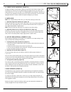
3. Setting Toe-in toe-out to zero (Figures 14, 15, 16 & 17)
NOTE– A wheelchair equipped with 0° camber plugs cannot have a toe-in toe-out
condition. This adjustment is only required when using 3°, 6° and 9° camber plugs.
Toe refers to how well the rear wheels of the chair are aligned relative to the ground. It
affects how well the chair will roll. Drag or rolling resistance is optimally minimized when
the wheel toe is set to zero.
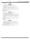
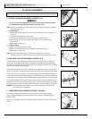
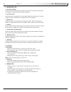
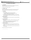
Setting the Toe to Zero (Figures 14 & 15)
Loosen the 2 cap screws (A) (1 per side) that secure the camber tube clamp. Observe the
ball in the level (B), and rotate the camber tube (C) until the ball is centered in the level.
The toe is now set at zero.
Before tightening the screws (A), make certain that the camber tube is centered left-to-
right relative to the wheelchair frame. There should be an equal gap on both sides or none
at all. Torque fasteners (A) to 144 in-lbs. (16.3 Nm).
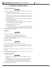
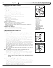
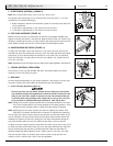
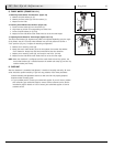
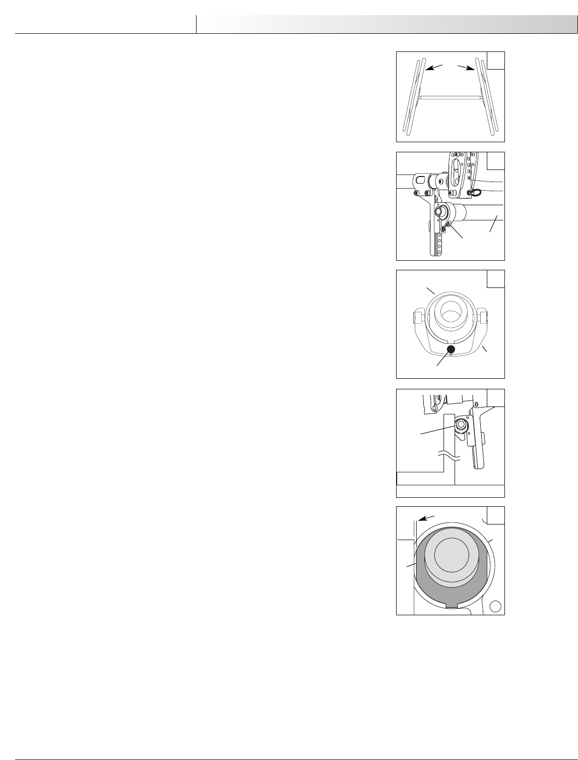
Setting the Toe to Zero– Alternative Method (Figures 14, 15, 16 & 17)
Place the entire wheelchair on a flat horizontal table or ground surface. Loosen the 2 cap
screws (A) (1 per side) that secure the camber tube clamp. Locate the flat surfaces on the
front and rear of the camber plugs (D). Place an object that is known to have an accurate
90° corner (such as a carpenters square, drafting triangle, etc.) down on the flat horizontal
surface and up against the flat of the camber plug. Rotate the camber tube and plug
assembly until the flat surface of the camber plug is parallel to the measuring tool.
Before tightening the screws (A), make certain that the camber tube is centered left-to-
right relative to the wheelchair frame. There should be an equal gap on both sides of the
wheelchair or none at all. Torque the fasteners to 144 in-lbs. (16.3 Nm).
H
13