


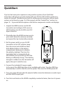
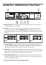
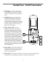
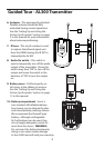
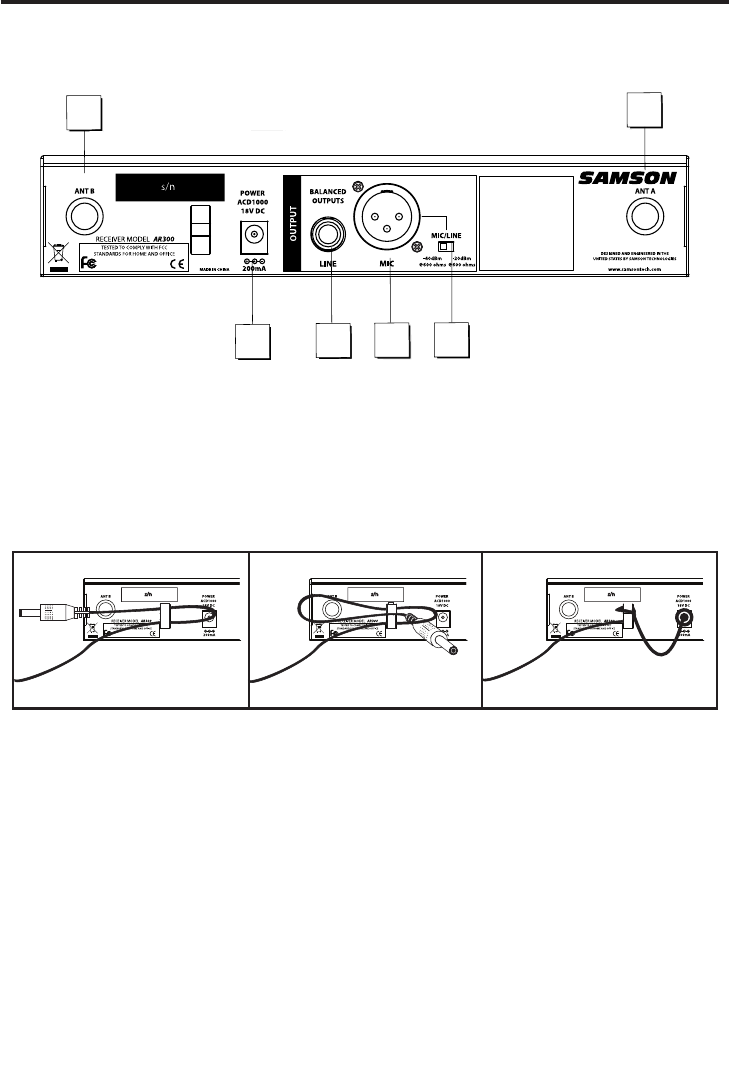
A: Antenna socket - D hole knockout for mounting the antennas to the rear panel
using the optional rear antenna kit.
B: DC input - Connect the supplied power adapter here, using the strain relief as
shown in the illustration below. WARNING: Do not substitute any other kind of
power adapter; doing so can cause severe damage to the AR300 and will void your
warranty.
C: 1/4-inch output* - Use this 1/4" jack when connecting the AR300 to your guitar
amp or to line level equipment. The output connection can be either balanced or
unbalanced. Wiring is as follows: tip hot, ring cold, sleeve ground.
D: XLR output* - Use this electronically balanced low impedance (600 Ohm) XLR jack
when connecting the AR300 to professional (+4) audio equipment. Pin wiring is as
follows: Pin 1 ground, Pin 2 high (hot), and Pin 3 low (cold).
E: Audio Output Level switch - Sets the audio output level attenuation of the XLR
output to -20 dBm (line level) or -40 dBm (mic level). See “Setting Up and Using the
AirLine Synth System” on page 15.
* If required, both outputs can be used simultaneously.
A
B
D
A
E
C
Guided Tour - AR300 Receiver / Rear Panel
-
6