


3
ASSEMBLY AND SET-UP
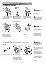
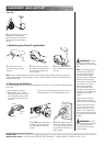
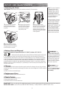
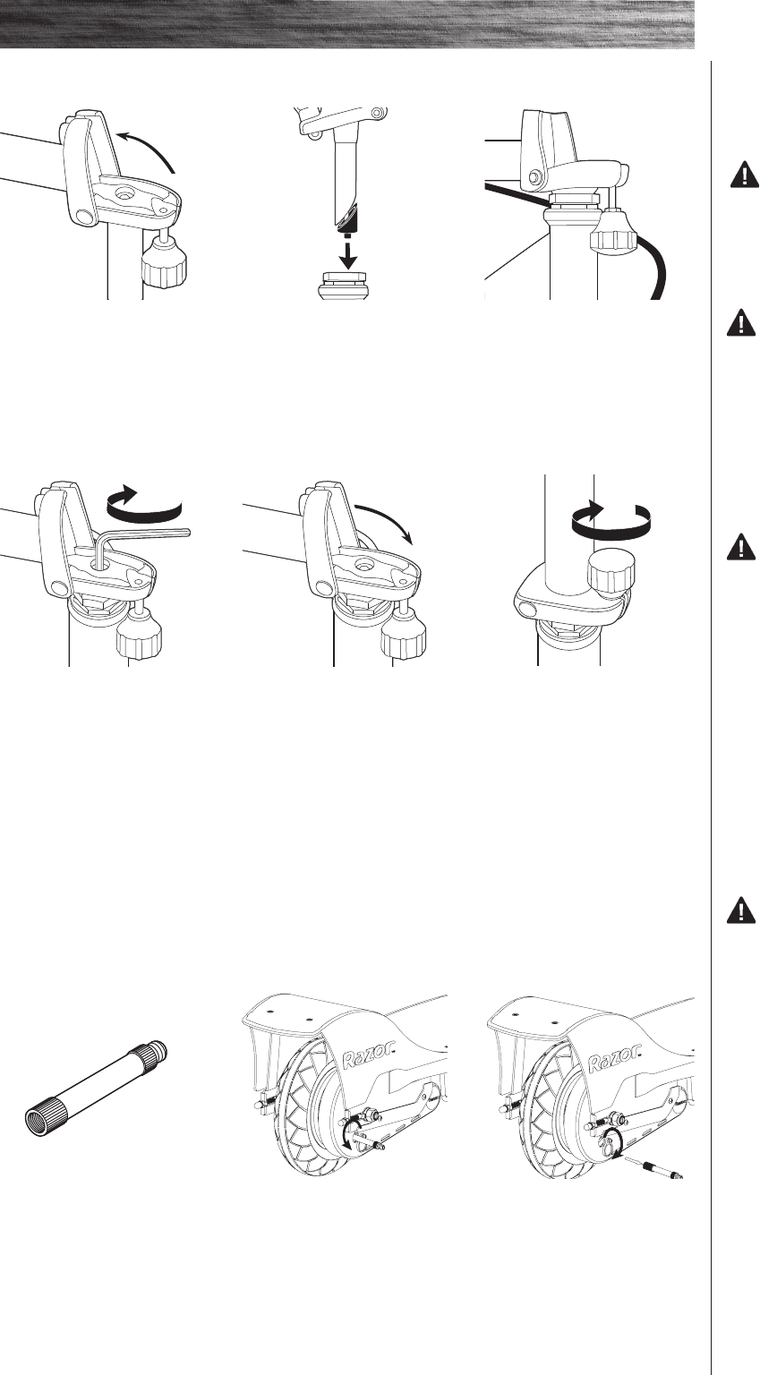
1 Use the valve extender/
adapter located in the end of
the right handlebar grip.
2 Open the round cover
located on the chain cover
by sliding the cover upward.
Align the opening in the drive
sprocket with the valve stem.
Thread the adapter completely
onto the valve stem and attach
the pump. Inflate to the PSI
indicated on the tire sidewall.
3 Remove valve adapter
immediately after inflating and
close the round cover.
q Inflating the Tires
Tires are inflated when shipped, but they invariably lose some pressure between the point of
manufacturing and your purchase. Always inflate tires to the correct PSI before first time use.
Rear Tire
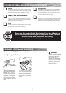
WARNING: Failure
to remove the valve adapter
after inflating will cause the
inner tube and/or adapter to
be severed by the rear drive
sprocket.
Note: If you lose the valve, one
can be purchased at almost any
auto parts store.
Note: The pressurized air
supplies found at gasoline
stations are designed to inflate
high-volume automobile tires.
If you decide to use such an air
supply to inflate your electric
scooter tires, first make sure
the pressure gauge is working,
then use very short bursts to
inflate to the correct PSI. If you
inadvertently over-inflate the
tire, release the excess pressure
immediately.
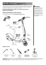
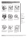
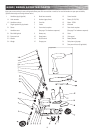
q Attaching the Handlebars
WARNING: Failure
to properly tighten the wedge
may allow the handlebars to
dislodge while riding and may
cause you to lose control and
fall. When correctly tightened,
the handlebars will not rotate
out of alignment with the
front wheel under normal
circumstances.
WARNING: Keep your
fingers clear of the pivoting
mechanism when folding or
unfolding the scooter, and make
sure others are standing clear.
Note: The cable and wire
assembly from the handlebar
must not wrap around the
steering tube or handlebar
as shown in step 3. Sharp
bends or twisting of the brake
cable can cause the brakes to
malfunction.
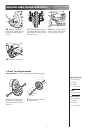
4 Using a 6mm hexagonal
key wrench, tighten the
wedge by turning the bolt
clockwise. The wedge is
properly tightened when the
handlebars cannot be twisted
out of alignment with the
front wheel.
5 Pivot the handlebar assem-
bly upright.
1 Loosen the locking knob and
swing to the 6 o’clock position
to unfold the handlebar.
2 Remove the plastic protec-
tor covering the base of the
handlebar assembly. Insert the
“quill” part of the handlebar
assembly into the fork. You may
have to loosen the wedge to
allow it to slip into the fork.
3 Slide the quill into the
fork until it bottoms on the
headset.
6 Swing the locking knob to
the 12 o’clock position and
tighten by hand as firmly as
possible.
WARNING: Failure
to recharge the battery at least
once a month may result in
a battery that will no longer
accept a charge.