


20 GROOVE
EENNGGLLIISSHH
0705/1/ST-000690620.EMS
12. Maintenance and Cleaning
The wheelchair should be wiped over once per week with a slightly
damp, not wet, cloth and any fluff or dust that has accumulated
around the motors should be blown or dusted away.
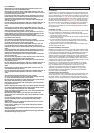
12.1. Tyre pressures
If pneumatic tyres are fitted to your wheelchair it is important to
regularly check the air pressure and for signs of wear.
The correct pressures are between the minimum of 137 kiloPascals
(20 psi, 1.37 bar) and the maximum 241 kiloPascals (35 psi, 2.41
bar) for rear and front wheels (see side of tyre).
The pressure will need to vary, depending on the weight of the
user.
IT IS IMPORTANT that front wheels are inflated to the same
pressure as a pair, and likewise the rear. The inflator pump
provides the safest method of inflating your wheelchair tyres
and the pressure can be checked with a standard motor
vehicle pressure gauge.
Do not inflate beyond the maximum allowed tyre pressure.
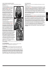
12.2. Tyre wear
When inspecting the tyres for signs of wear, look for significant
scuff marks, cuts and a diminished tyre tread. Tyres will need to be
changed when the tread cannot be seen over the complete surface
of the tyre.
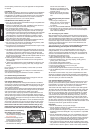
12.3. Electrical connections
When inspecting electrical connections, pay attention to the bat-
tery connections, the connection of batteries to power loom and
plug in sockets for the joystick, control box and lights and indica-
tors.
12.4. Upholstery/seating
Tears, dents, wearing or slackening of upholstery particularly near
to metal could result in poor posture or lower levels of comfort and
pressure relief.
12.5. Authorised Sunrise Medical service agents
The annual full service must be performed by an approved Sunrise
Medical Service Agent. For a list of approved service agents in
your area please contact Sunrise Medical Service Centre on this
telephone number: 01384 44 66 66
12.6. Storage
When storing your powerchair for long periods of time (in excess of
one week), first fully charge, and then disconnect the batteries, to
minimise battery discharge. Never store your wheelchair in direct
sunlight or in a damp/outdoor environment. It might bleach plastic
parts and components.
12.7. GROOVE maintenance and routine
Complete inspection, safety check and service should be made by
an authorised Sunrise Medical supplier or it may void warranty!
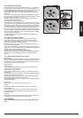
12.8. Battery installation for the GROOVE wheelchair
12.8.1. How to connect the cables to the batteries
To access batteries refer to part 9.1 in this manual.
The red cable always goes to the positive terminal (+) of one bat-
tery. The black cable always goes to the negative terminal (-) of the
other battery. One of the yellow cables goes to the negative pole of
one battery (see label on cable) and the other yellow cable goes to
the positive pole of the other battery (see label on cable), linking
both batteries serially with the red connectors to give a supply of
24 volts.
It is better to direct the cable terminals towards the interior of the
box to avoid risk of contact with the outer box.
If you are in any doubt, please contact your Sunrise Medical sup-
plier. For further information please refer to the technical manual.
Parts in the battery box:
• Supporting plate for wheelchair controller and electric modules.
• Conical-shaped terminals for batteries with cylindrical terminals.
• Two installation cables. The black plate has holes and is design-
ed to support special controls. It should be placed in the space
between the two batteries and fixed with two bolts on each top
side.
Connect the batteries with the terminals opposing the centre of the
plate to avoid possible contact with it.
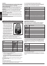
CAUTION:
Before connecting the battery terminals it is very important to
connect together the two connectors that join the cables. This
way, if one cable is connected wrongly, it will produce a small
spark indicating that something is wrong.
CAUTION:
The cables are connected first and then the connectors
together, if there is a problem, the installation will ignite, caus-
ing major damage to the batteries.
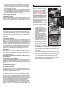
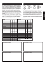
The red cable always goes to the positive terminal (+) of one bat-
tery. The black cable always goes
to the negative terminal (-) of the
other battery. One of the yellow
cables goes to the negative pole of
one battery (see label on cable)
and the other yellow cable goes to
the positive pole of the other bat-
tery (see label on cable), linking
both batteries serially with the red
connectors (Fig. 74) to give a
supply of 24 volts.
It is better to direct the cable terminals towards the interior of the
box to avoid risk of contact with the outer box.
If you are in any doubt, please contact Sunrise Medical Tel (+44)
1384 44 66 66.
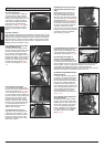
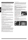
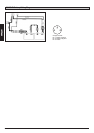
12.9. Controller access
For the GROOVE F/R please follow the “battery access instruction
in section 9. This gives also access to the Motor Control Module
(Fig. 75) on GROOVE F/R.
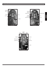
To access the controller on the GROOVE M take the rear shroud on
the base between the rear castor wheels of (Fig. 76).
For further information please refer to the technical manual.
Fig. 74
Fig. 75 Fig. 76