


16 GROOVE
EENNGGLLIISSHH
0705/1/ST-000690620.EMS
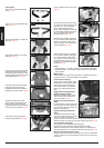
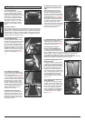
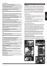
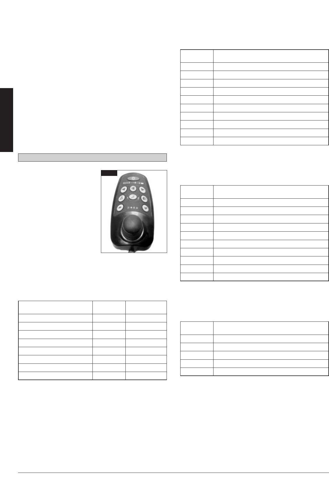
8. The Delphi QC Hand Control
• On/off button: This connects or
disconnects the entire electronic
system, which supplies energy
to the motors. Do not use this
button to stop the chair except
in case of an emergency. Doing
so may damage the wheelchair.
• Battery Gauge: This indicates
that the wheelchair is under
power. It also indicates any fault
there may be in functioning. The
number of lights flashing indica-
tes the fault type. (See "Battery
Gauge” in this manual.)
• Speed indicator: This indicates
the maximum speed set for the
wheelchair. There are four
speeds predefined. The first is the lowest, the last is the highest.
• Speed down button: Decrease the maximum speed setting.
• Speed up button: Increase the maximum speed setting.
• Horn switch: Initiates the Horn when pressed.
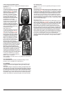
• Battery Gauge: If it remains lit, this means that the System is
working normally. It flashes to indicate any fault that may have
arisen.
Slow flashing of the Red LED indicates that the Batteries should be
recharged as soon as it is feasibly possible.
•To operate the lights and indicators press the relevant button
for the on and off operation.
•To operate the actuators press the Mode button in the centre of
the Joystick. A left or right movement of the joystick selects the
desired seat function. A green LED will indicate the option
selected.
Moving the joystick forwards and backwards changes the angle of
the seat option chosen.
By pressing the actuator button again you return into the drive
mode.
8.1. Controller Diagnostics
The following list shows Diagnostic information that applies to both
the Delphi Consumer (QR) and Rehab Control Systems:
8.1.1. Drive System Failures (QC and QR controller)
Drive System failures are indicated by the Mode LED flashing Red.
In conjunction with this flashing red LED, the Battery Gauge will
flash steadily in one of the following combinations:
8.1.2. Seating System Failures
(QMAC failures on QR System Only)
Seating System failures are indicated by the Mode LED flashing
Green. In conjunction with this flashing Green LED, the Battery
Gauge will flash steadily in one of the following combinations:
8.1.3. Environmental Control System Failures (QR System Only)
Environmental Control System failures are indicated by the Mode
LED flashing Amber. In conjunction with this flashing Amber LED,
the Battery Gauge will flash steadily in one of the following combi-
nations:
8.1.4. Lighting System Failures
Failures in the Lighting system are indicated by double speed flas-
hing of the LED next to the relevant Lighting Button on the Remote
Control
Approximate battery state of LED- Display
charge Display state
Battery charge ≥ 80% steady
80% ≥ Battery charge ≥ 70% steady
70% ≥ Battery charge ≥ 60% steady
60% ≥ Battery charge ≥ 50% steady
50% ≥ Battery charge ≥ 40% steady
40% ≥ Battery charge ≥ 30% steady
30% ≥ Battery charge ≥ 20% steady
Battery charge ≤ 20% flash 1,5 Hz
LED- Error description
Display
Motor Controller Internal Module Error
Module Communication Error
Input Device Out of Neutral at Power On
Park Brake Open Circuit Error
Right Motor Open Circuit OR Right Motor Encoder Error
Left Motor Open Circuit OR Left Motor Encoder Error
Battery Under Voltage OR Battery Over Voltage Error
Motor Controller High Temperature Warning
Invalid System Configuration Error
Drive Lockout External Source
LED- Error description
Display
QR-MAC Internal Module Error
Module Communication Error
QR-MAX Hex Switch Not Neutral at Power On
QR-MAX Home Switch Not Neutral at Power On
Actuator Encoder Error
Actuator Over Current Error
Battery Under Voltage OR Battery Over Voltage Error
QR-MAC High Temperature Warning
Invalid System Configuration Error
Drive Lockout External Source
LED- Error description
Display
QR-ECM Internal Module Error
Module Communication Error
Battery Under Voltage OR Battery Over Voltage Error
Invalid System Configuration Error
Drive Lockout External Source
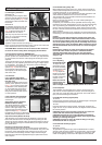
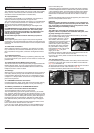
Fig. 61
WARNING
Before adjusting the swing-away arm, switch off the controller
to avoid accidental displacement of the joystick which would
cause unwanted movement of your wheelchair.
Keep your fingers and clothing, etc. clear while operating the
swing-away mechanism.
Be aware that the width of you chair has increased if the
swing-away arm is out and you may not get between certain
obstacles.
Do not hang any items on or over the parallel swing-away
remote assembly as this could damage the swing-away
mechanism.
When transferring to and from the wheelchair do not use the
remote as a means of support.
Keep fingers, clothing, etc. clear of the swing-away mecha-
nism at all times.
Ensure the power is switched off while adjusting the parallel
swing-away arm.
Only operate the wheelchair at low manoeuvring speed when
the parallel swing-away is in use.