


Quantum 1402 www.quantumrehab.com 23
V. COMFORT ADJUSTMENTS
COMFORT ADJUSTMENTS
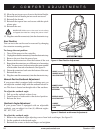
After becoming familiar with your power chair’s operation, you may find the need to make some adjustments to increase
your comfort, such as seat height and angle, armrest angle, foot platform height and angle, and the controller’s position.
NOTE: If your power chair is equipped with a Specialty Seat, Synergy Seat, or Synergy TRU-Balance, refer to
the information provided in separate manuals. If your power chair is equipped with a contoured seating sys-
tem, refer to the following information.
WARNING! If your power chair was configured at your Quantum Rehab Specialist, please consult
your healthcare professional before changing the seat position or making any other adjustment.
Some adjustments may degrade your power chair’s performance and safety by changing its
center of gravity.
WARNING! Some power chair components are heavy. You may need assistance to lift or carry
them. Please refer to the specifications table for specific component weights before you
disassemble the power chair.
WARNING! Remove the occupant from the power chair before making any adjustments.
You may need the following to make comfort adjust-
ments:
! metric/standard hex key set
! metric/standard socket set and ratchet
! adjustable wrench
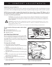
Seat Height/Angle Adjustment
The seat is attached to the power base through the UMS.
You can change the seat height by raising the front and
rear trapeze bars. If you raise or lower only one set of
trapeze bars (front or rear), you can also change the seat
base angle (dump).
To change the seat height:
1. Turn off the power to the controller.
2. Unplug the controller connector(s) from the electron-
ics tray.
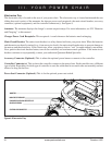
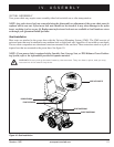
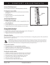
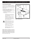
3. Flip up the seat latch safety. See figure 12.
4. Squeeze the seat latch and release the seat from the
front trapeze bar.
5. Slide the seat forward and remove it from the power
base.
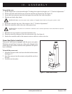
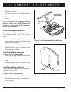
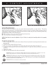
6. Remove the quick-release pins from the seat towers
(front and rear). See figure 13.
7. Remove both trapeze bars from the seat towers.
8. Lift off the shroud
9. Remove the ball detent pin from each of the four seat
towers. See figure 13.
QUICK-RELEASE PINS
TRAPEZE BARS
BALL DETENT PINS
SEAT TOWER
Figure 12. Seat Latch Safety (Disengaged)
Figure 13. Seat Height Adjustment