


20
www.pridemobility.com Pride LX Series/Rev B/Feb 03
V. YOUR PRIDE LX
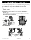
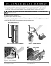
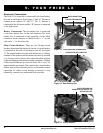
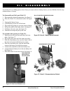
Figure 15. Front Electrical Connections
Electronic Connections
The Pride LXs controller is connected to the front battery
box and to each motor. See figures 15 and 16. The motor
connectors are marked L and R. The L harness is
connected to the left motor and the R harness is connected
to the right motor.
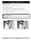
Battery Connections: The rear battery box is connected
to the front battery box via the red connector. The front
battery box is connected to the controller via the black
connector. Each connector is labelled with a + on one
side and a - on the other side.
Main Circuit Breakers: There are two 30-amp circuit
breakers that protect the electrical circuits. A circuit breaker
is mounted on the side of each battery box lid. See figure
17. The circuit breaker is in-line with the positive (+) battery
terminal. If the batteries and the motors are heavily strained
(e.g., from excessive loads), these circuit breakers will trip
to prevent damage to the motors and the electronics. If either
of the circuit breakers trip, allow the Pride LX to rest for
approximately one minute. Then, push in the circuit breaker
button, turn on the controller power, and continue normal
operation. If either circuit breaker continues to trip
repeatedly, contact your authorized Pride provider.
Figure 16. Rear Battery Box
MOTOR CONNECTORS
CONTROLLER CONNECTOR
Figure 17. Circuit Breaker
REAR BATTERY BOX CONNECTOR
CIRCUIT BREAKERS ARE
MOUNTED ON THE SIDES OF THE
BATTERY BOX LIDS.