


34 www.pridemobility.com Jet 3/Rev I/Feb03
PILOT CONTROLLER
The electronic controller is what you use to operate your power chair. It takes the battery voltage and sends it to
the appropriate system. The electronic controller also enables you to monitor battery charge, electronic controller
functions, and the condition of your electrical system. Also, it may be used to control some optional systems such
as power elevating seats and lights.
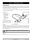
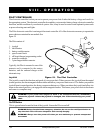
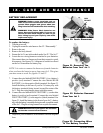
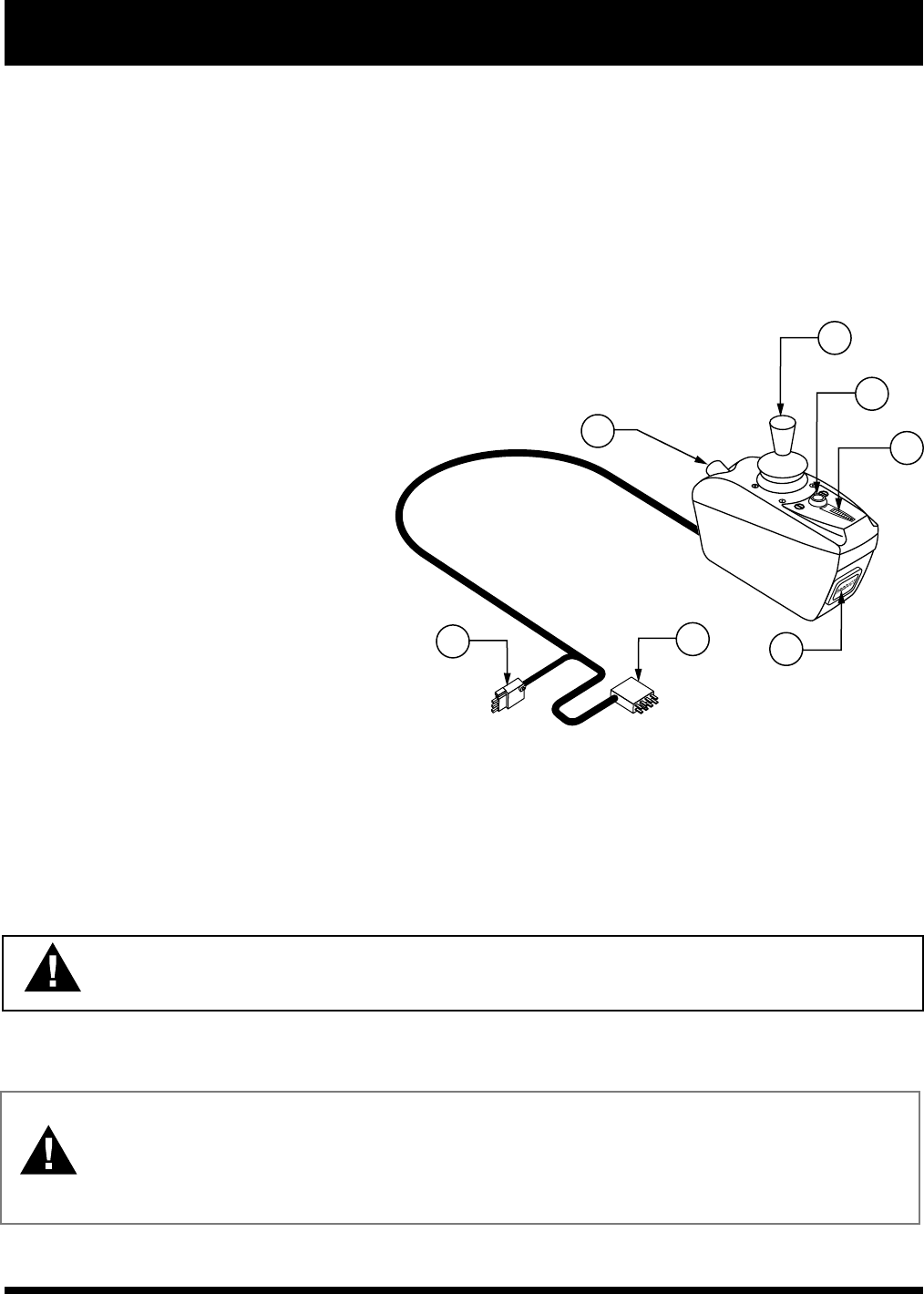
The Pilot electronic controller is an integral electronic controller. All of the electronics necessary to operate the
power chair are contained in one module. See
figure 19.
The Pilot consists of:
1. joystick
2. on/off button
3. battery condition meter
4. speed control knob
5. off-board charger/programming socket
6. controller connector
7. 3-pin charger inhibit connector
Typically, the Pilot is mounted to one of the
armrests and is connected to the motors,
batteries, and the onboard charger at the
electronics tray.
Joystick
The joystick controls the direction and speed of your power chair. When you move the joystick from the neutral
(center) position, the electromagnetic brakes release and allow your power chair to move. The further you push the
joystick from its neutral position, the faster your power chair moves. When you release the joystick and allow it to
return to the netural position, you engage the electromagnetic brakes. This causes your power chair to decelerate
and come to a complete stop.
WARNING! If your power chair begins to move in an unexpected manner, immediately
release the joystick. Unless the joystick is damaged, this action should stop your power
chair.
On/Off Button
This is a green button located in front of the joystick. It turns the Pilot on and off.
WARNING! Unless faced with an emergency situation, do not use the on/off push button to
stop the chair. This will cause the power chair to stop abruptly.
WARNING! Always turn the power off when you are stationary to prevent unexpected
movement.
VIII. OPERATION
2
3
4
1
7
6
5
Figure 19. The Pilot Controller