


Jet 3/Rev I/Feb03 www.pridemobility.com 31
VIII. OPERATION
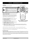
On/Off Key
The on/off key turns the VSI on and off.
WARNING! Unless faced with an emergency
situation, do not use the on/off key to stop the
chair. This will cause the power chair to stop
abruptly.
WARNING! Always turn the power off when you
are stationary to prevent unexpected move-
ment.
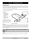
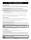
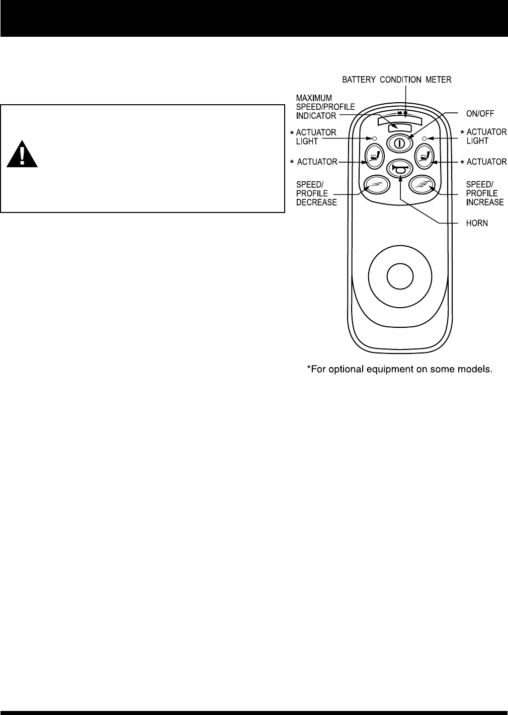
Battery Condition Meter
The battery condition meter is located in front of the joystick.
See figure 18. This is a 10-segment illuminated display that
indicates that the VSI is turned on and also gives the battery
status, the VSI status, and the electrical system status.
n Red, yellow, and green lights lit: Battery charged; VSI
and electrical system OK.
n Red and yellow lights lit: Charge battery if possible;
VSI and electrical system OK.
n Red lights only lit or slow flash: Charge battery as soon
as possible; VSI and electrical system OK.
n Rapid flash of lights: Indicates a fault in the VSI or the
electrical system. Refer to VSI Error Codes.
n Ripple up and down of lights: The joystick was not in the neutral position when the controller was
turned on. If you get ripple up and down of lights, turn off the controller, allow the joystick to return
to the neutral position, then turn on the controller.
NOTE: If you still get ripple up and down of lights, contact your authorized Pride provider.
NOTE: When the batteries approach a discharged state, the first red light will begin to slowly flash,
reminding you the batteries need to be charged immediately!
Speed/Profile Keys
There are two keys that control either the speed or the profile. See figure 18. This depends on how your VSI was
programmed. Press the speed/profile increase key to increase the speed or change the profile. Press the speed/
profile decrease key to decrease the speed or change the profile. The speed/profile setting is displayed on the
maximum speed/profile indicator. If your power chair was programmed with a drive profile, contact your authorized
Pride provider for more information.
Figure 18. VSI Controller Keypad