


22 www.pridemobility.com Select Traveller
V. COMFORT ADJUSTMENTS
COMFORT ADJUSTMENTS
After becoming familiar with your power chair’s operation, you may find the need to make some adjustments to
increase your comfort, such as seat height, armrest width, foot platform depth, and controller position. Use the
steps below to make comfort adjustments.
WARNING! The center of gravity of your power chair was factory set to a position that meets the
needs of the demographic majority of users. Your authorized Pride Provider has evaluated your
power chair and made any necessary adjustments to suit your specific requirements. Do not
change your seating configuration without first contacting Pride Mobility Products or your
authorized Pride Provider.
WARNING! Some power chair components are heavy. You may need assistance to lift or carry
them. Please refer to “Appendix I – Specifications” for specific component weights before you
disassemble the power chair.
WARNING! Remove the occupant from the power chair before making any adjustments.
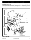
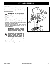
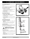
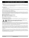
Figure 10. Seat Height Adjustment
SEAT PEDESTAL
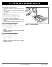
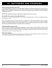
Figure 11. Quick Release Fastener Operation
LEVER (OPEN)
UNCLAMPED
BOLT
NUT
CAM
LEVER (FULLY CLOSED)
CLAMPED
Seat Height Adjustment
You can adjust the seat to two different heights in 1-in.
(2.54-cm) increments. Seat height adjustment requires
the removal of the battery box.
To change the seat height:
1. Turn off the power to the controller.
2. Disconnect the controller connector from the
power base.
3. Remove the seat.
4. Loosen the quick release fastener. See figure 10.
5. Remove the safety snap pin from the seat pedestal.
6. Reposition the seat pedestal to the desired height.
7. Reinstall the seat pedestal safety snap pin.
8. Tighten the quick release fastener. See figure 11.
9. Reinstall the seat.
10. Reconnect the controller connector.
Quick Release Fasteners
The quick release fastener removes excess play in the
seat pedestal. See figure 10. The quick release fastener
consists of a bolt, a lever, and a nut. See figure 11. The
lever has a cam on the end that allows it to clamp into
place. The quick release fastener has two states: clamped
and unclamped. When the lever is open, the quick
release fastener is unclamped. When the lever is closed,
the quick release fastener is clamped.
To clamp the quick release fastener:
1. Make sure the lever is in the open position.
2. Turn the nut clockwise until it is snug.
3. Rotate the lever until it is in the fully closed
position.
NOTE: If the lever will not rotate to the fully closed
position, then turn the nut counterclockwise one-
quarter or one-half turn.
QUICK
RELEASE
FASTENER
SAFETY
SNAP PIN