


Exterior Lift System www.pridemobility.com 9
III. INSTALLATION
EXTERIOR LIFT SYSTEM INSTALLATION
The Exterior Lift System is designed to be easily installed into any vehicle equipped with a Class 2 or Class 3 hitch
receiver. The hitch receiver should be installed no higher than 21 in. (53 cm) from the bottom of the hitch tube to the
ground.
NOTE: Once installed, the lift system may obstruct the view of the vehicle license plate. Research the
local laws for license plate obstruction in your area and install the license plate kit. Contact your autho-
rized Pride Provider for more information.
WARNING! Prevent product and/or vehicle damage! The Exterior Lift should be installed
by an authorized service technician only.
Follow these steps to install the Exterior Lift System:
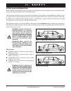
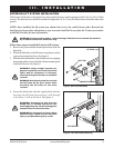
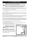
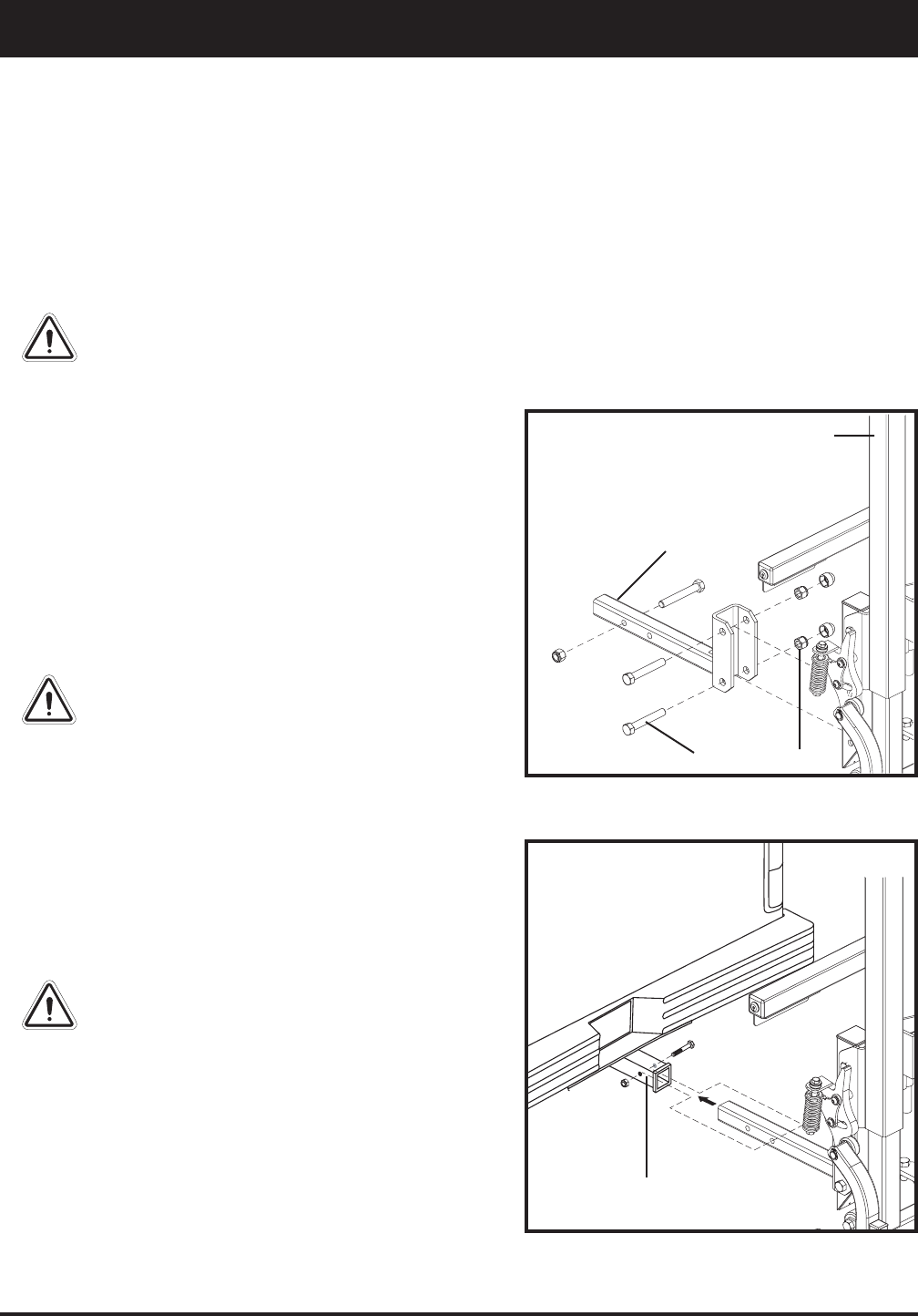
1. Remove the preassembled mounting hardware from the
hitch tube.
2. Mount the hitch tube to the lift frame using the previously
removed mounting hardware. See figure 4.
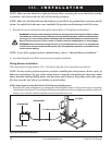
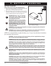
3. Slide the hitch tube into the vehicle hitch receiver, aligning
the mounting hole closest to the lift with the mounting hole
in the hitch receiver. See figure 5.
WARNING! Lifting weight beyond your
physical capability can result in personal
injury. Ask for assistance if necessary
when attaching the lift frame to the hitch
receiver.
WARNING! Avoid pinch points! Do not hold
the lift frame by the pivot points when
mounting the lift frame to the hitch
receiver.
4. Secure the hitch tube with the supplied bolt and nut,
inserting the bolt from the passenger’s side through
to the driver’s side of the hitch. See figure 5.
WARNING! Threading the bolt from the
wrong side or allowing the bolt to turn
while tightening the nut will dislodge the
threaded insert in the hitch tube.
WARNING! Do not attach a Class 2 hitch
tube to a Class 3 hitch receiver. Personal
injury or product damage may result.
Figure 4. Hitch Tube Assembly
Figure 5. Lift Frame Vehicle Mounting
HITCH TUBE
LIFT FRAME
HITCH RECEIVER
MOUNTING HARDWARE