


Exterior Lift System www.pridemobility.com 13
IV. OPERATION
WARNING! For lift systems equipped with the automatic lock-down arm, do not attempt to
adjust the pressure of the arm. This feature has been configured by your authorized Pride
Provider to meet your needs and requires no further adjustment.
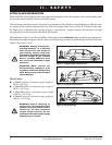
WARNING! If your scooter is equipped with pneumatic drive tires, make sure the tires are
inflated to the recommended pressure labeled on the tire sidewall. This will ensure that
the scooter is at the correct deck height for proper lock-down arm positioning.
NOTE: Inspect the tie-down straps before each use to ensure there are no signs of fraying or wear.
Ensure that the mobility device is secured properly before transport. Pride is not liable for damage or
loss resulting from improper securing of a mobility device.
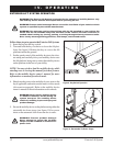
6. Turn and hold the key counterclockwise to raise the lift. See figure 9. Continue to raise the lift until the motor
stops, then release the key.
NOTE: As the lift platform rises, the automatic lock-down arm activates to secure the scooter to the lift
platform. You may need to adjust the scooter tiller position to prevent interference with the smooth
operation of the automatic lock-down arm.
NOTE: The motor will stop automatically at the top of its stroke and will emit a clicking sound.
Release the key immediately upon hearing this sound, then turn the key counterclockwise one more
time for no more than 2 seconds to ensure the platform is in the fully raised position.
NOTE: Pay attention to the path of the lift platform during operation. Make sure the lift does not rub
against or interfere with the vehicle in any way. If you notice any contact between the lift platform and
the vehicle, stop lift operation immediately and contact your authorized Pride Provider for assistance.
Follow these steps to remove a mobility device from the Exterior Lift System:
1. Lower the lift platform to the ground.
2. Unfasten the tie-down straps or allow the lock-down arm to automatically return to the vertical position.
3. Unload the mobility device from the lift platform.
4. Raise the lift platform for storage, noting that it will automatically fold into a stowed position.
5. Remove the key from the lift system when it is not in use.
WARNING! Do not attempt to manually pull
the lift platform down from the stowed
position. Doing so will result in product
damage and will void the product
warranty.
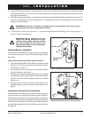
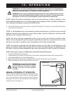
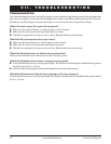
MANUAL EXTERIOR LIFT OPERATION
The lift system is equipped with a manual crank that serves as
backup in the event of a power failure. Using the supplied
tool, rotate the manual crank (located on top of the motor
housing) clockwise or counterclockwise to move the plat-
form up or down. See figure 11.
Figure 11. Manual Crank Operation
MANUAL CRANK
MOTOR HOUSING