


Exterior Lift System www.pridemobility.com 11
III. INSTALLATION
2. Conceal the harness behind or under the interior panels of the vehicle (there should be existing holes). Be
certain that the harness is protected with a rubber grommet when passing it through the metal panels and into
the engine compartment.
3. Inside the engine compartment, secure the harness to the firewall and the inner fender with plastic wire ties. Use
care not to cause abrasions to the wiring harness. It is important to secure the wiring harness at various points
along its run of the vehicle.
WARNING! Do not cut or shorten the wiring harness. If the harness is too long, coil the
excess wire and secure it with plastic wire ties.
4. Connect the red wire to the positive (+) terminal and the black (grounding) wire to the negative (-)
terminal of the vehicle battery.
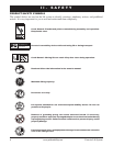
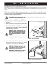
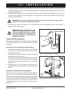
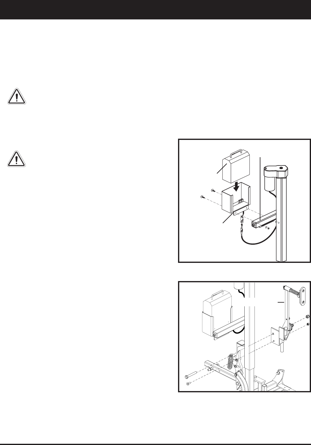
Figure 7. Onboard Battery Installation
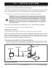
Figure 8. Automatic Lock-down Arm Installation
BATTERY CASE
BRACKET
ACCESSORY BRACKET
LOCK-DOWN ARM
WARNING! Before operating the lift,
inspect the wiring harness for proper
routing and grounding. Improper routing
can cause damage to the harness, and
improper grounding can cause damage to
the electrical system.
Onboard Battery Installation
The optional onboard battery is designed for easy installation
as it does not require any wires to be routed through or under
the vehicle.
Follow these steps to install the onboard battery:
1. Align the mounting holes in the battery case bracket with
those in the accessory bracket located under the key
switch tube. See figure 7.
2. Secure the battery case to the accessory bracket with the
supplied hardware. See figure 7.
3. Insert the onboard battery into the battery case, making
sure that the connector on the bottom of the battery aligns
and fully connects with the mating connector inside the
battery case.
4. Plug the battery cord on the bottom of the battery case
into the mating connector running from the motor. See
figure 7.
Automatic Lock-down Arm Installation
The automatic lock-down arm is a safety feature designed to
secure scooters to the lift platform during vehicle transport.
The automatic lock-down arm will come fully assembled. In
order to secure it to the frame, align the lock-down arm bracket
with the holes at the back of the lift frame under the tilt bar
and install the supplied hardware to lock the assembly in place.
See figure 8.
BATTERY CASE