


28 www.pridemobility.com Quantum 600 Series
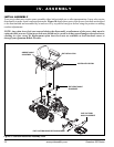
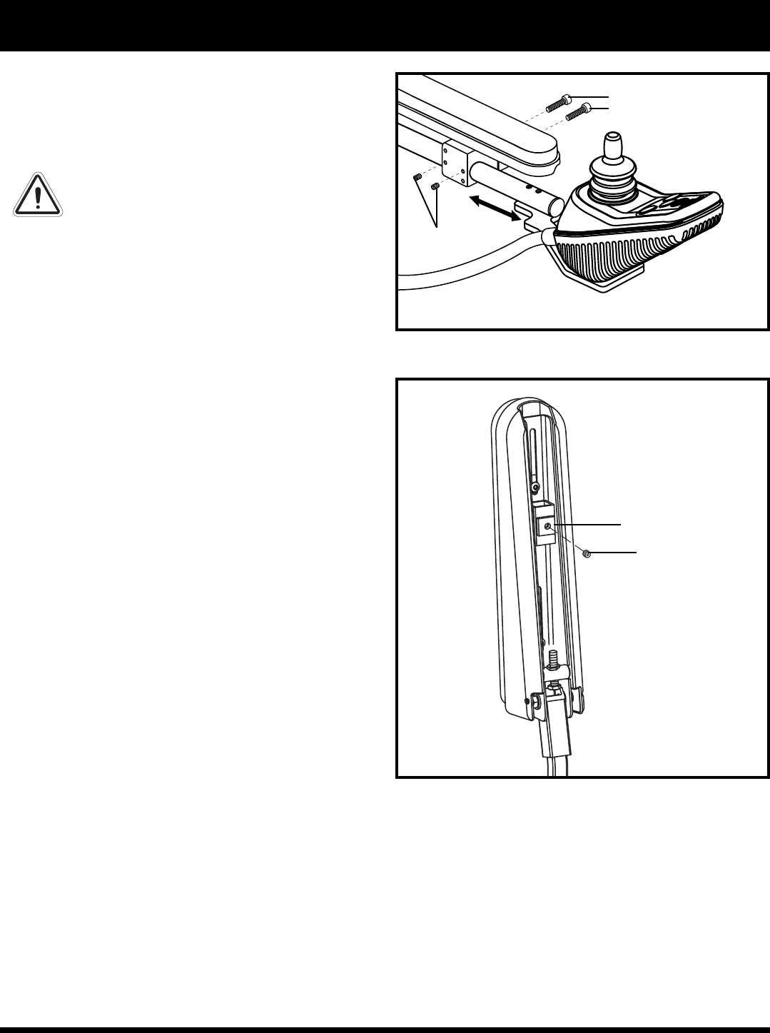
SETSCREWS
MOUNTING
SCREWS
V. COMFORT ADJUSTMENTS
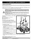
Controller Position
You can move the controller in toward or out away
from the armrest, or change the position of the
controller for either left-hand or right-hand use.
WARNING! Do not place the controller
harness so that it can be pinched in
the seat frame or the power base
frame.
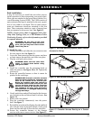
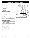
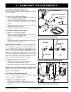
To extend the controller:
1. Flip up the armrest so it is perpendicular to the floor.
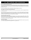
2. Loosen the setscrew on the controller bracket. See
figure 19.
3. Slide the controller into or out of the armrest to the
desired position.
4. Tighten the setscrew to secure the controller.
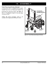
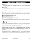
NOTE: If your power chair is equipped with a
Specialty Seat, Synergy Seat, or TRU-Balance Power
Positioning System, loosen the setscrews in the
mounting block, slide the controller in or out to the
desired position, then tighten the setscrews. See
figure 18.
To change the controller position:
1. Turn off the power to the controller.
2. Gently push down and pull backward at the harness
access point on the rear shroud until it releases. See
figure 12.
3. Unplug the controller connector from the power base.
4. Remove any wire ties securing the controller har-
ness to the armrest.
5. Flip up the armrest so it is perpendicular to the floor.
6. Loosen the setscrew on the controller bracket
7. Slide the controller out of the armrest.
8. Loosen the setscrew in the other armrest.
9. Place the controller in the other armrest.
10. Tighten the setscrew in each armrest.
11. Route the controller harness to the back of the
power base and plug in the controller.
12. Reinstall the rear shroud by aligning the side and back
tabs with the holes in the main shroud. Gently push
down and forward until all four tabs lock into place.
13. Secure the controller harness to the armrest with
wire ties.
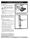
NOTE: If your power chair is equipped with a Spe-
cialty Seat, Synergy Seat, or TRU-Balance Power
Positioning System, loosen the mounting screws in
the mounting block, transfer the mounting block and
controller to the opposite armrest, and tighten the
mounting screws. See figure 18.
Figure 18. Controller Position Mounting Bracket
Figure 19. Underside of Armrest
SETSCREW
CONTROLLER BRACKET