


22 www.pridemobility.com Jazzy 1103 Ultra
IV. ASSEMBLY
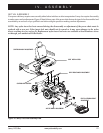
SEAT INSTALLATION
It may be necessary to install the seat either prior to initial opera-
tion or after transporting your power chair. Most seats are at-
tached to the power base with the Universal Mounting System
(UMS). The UMS consists of universal parts that may be at-
tached to any medium-back or high-back seat, regardless of seat
width or seat depth. The two main components are aluminum
extrusions mounted to the seat base. These extrusions attach to a
pair of trapeze bars that are mounted to the power base.
WARNING! Do not pick up the seat frame by
the armrests. They are free to pivot, and you
may lose control of the seat if they do so.
To install the seat:
1. Set the trapeze bars to the desired height or raise the power
elevating seat actuator 5 cm (2 in.) to allow for sufficient
clearance. To change the trapeze bar height, see V. “Com-
fort Adjustments.”
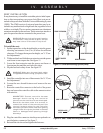
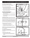
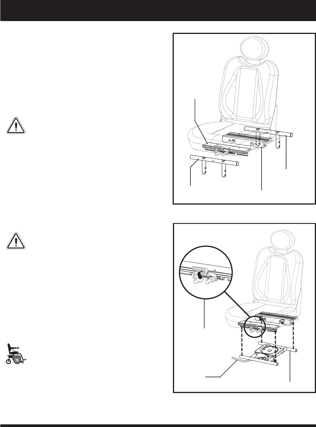
2. Tilt the seat back and slide the rear extrusion onto the power
seat frame or rear trapeze bar. See figure 11.
3. Lower the front extrusion onto the power seat frame or
front trapeze bar until the seat locks into place.
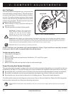
4. Flip the seat latch safety down. See figure 12.
WARNING! Make sure the seat latch safety
is flipped down before using your power chair.
5. Install the controller into one of the armrests. See V. “Com-
fort Adjustments.”
6. Loosen the rear shroud fasteners and remove the rear
shroud.
7. Route the controller connector to the back of the power
base and secure the controller cable to the armrest receiver
with wire ties.
MANDATORY! Prevent controller harness
damage! Avoid routing the controller
harness on the outside of the armrest pad.
Route the harness under the armrest or
toward the inside of the armrest pad. Use
correct tie-down points for the controller
harness to prevent the harness from getting
caught in the drive tyres, pinched in the seat
frame or damaged when passing through
doorways.
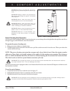
8. Plug the controller connectors into the power pod and con-
nect the battery connector. See figure 7.
9. Reinstall the rear shroud and tighten the fasteners.
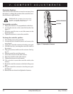
Figure 11. Universal Mounting System (UMS)
Figure 12. UMS - Power Elevating Seat System
FRICTION LOCK
LEVER
SEAT LATCH SAFETY
POWER SEAT FRAME
FRONT TRAPEZE
BAR
FRONT EXTRUSION
REAR EXTRUSION
REAR TRAPEZE BAR