


Objectives for fixed stage upright
microscopes (using WI-UCD, WI-DICTHRA)
14
Item Specifications
Laser light Visible light laser source Select from the following laser, to mounted on laser combiner
source Multi-line Ar laser (458nm, 488nm, 515nm, Total 40mW), Ar laser (488nm,10mW), Kr laser (568nm, 10mW),
HeNe (G) laser (543nm,1mW), HeNe (R) laser (633nm,10mW), LD405 (405nm, 25mW), LD440 (440nm, 5.3mW)
Laser combiner Each laser light path is equipped with a continuously variable neutral density filter or AOTF
All laser lines are combined to apsis along the same fiber optic
Scanning unit Scanning method Galvanometer mirror scanners (both X and Y)
Field number 20 (10 with use of LD405 laser)
Pinhole 5-position pinhole turret
Image memory and Standard scanning mode: 256 x 256 (0.45s) - 2048 x 2048 (10.835s)
scanning speed Bi-directional high-speed scanning mode: 512 x 512 (0.25s) (Simultaneous scanning of up to 2 channels)
Image channel Selectable from 2-channel (fluorescence) or 2-channel (fluorescence) + 1-channel (transmitted light)
3-channel (fluorescence) using virtual channel
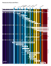
Selection of filters according to staining
Manual selection
Scanning modes XY, XYZ, XYT, XYZT, XZ, XT, XZT, point, Line-t, free line-t, line-z, free line-z, Clip, ZoomIn
Image depth resolution 12-bit (=4096 grey levels)
Zoom 1X-10X
Z-drive Step motor/Minimum step 10nm (BX61, BX61WI and IX81 combination), 25nm (other microscope combination)
Microscopes Upright BX51, BX61, BX51WI, BX61WI
Inverted (special laser safe frame) IX81FVSF, IX71FVSF (side port)
External trans- Transmitted light illumination unit External halogen light source connected to microscope via fiber cable
mitted light unit Transmitted light detector External detector unit with built-in photomultiplier Connected to microscope frame via fiber cable
Fluorescence illumination unit Connect to external mercury light source and microscope via fiber cable
Standard equipment of FV300-BX51, FV-300-BX61, FV300-BX51WI, FV300-BX61WI
PC with system control boards PC-AT compatible machine/OS: Windows XP (English version)/ 1GB memory (can be expanded to a maximum of 4GB)
CPU: Pentium 4, over 2.8GHz, Special I/F board/image capture: PCI bus
Graphic board: G450_Dual 32MB
Hard disk: 80GB 7200rpm_ID (ATA100) with DVD-ROM
Monitor: Two 19” LCD monitors are recommended, each able to display 1280x1024 images in full color (16.77 million colors)
LAN: On board
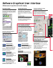
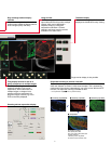
Fluoview Image acquisition Scanning condition setting: image size, scanning speed, zoom, panning etc.
application Real-time image calculation: Kalman filtering, peak integration,
software
Hardware control Laser, scanning unit, microscope
Each image display: Single-channel side-by- side, merge, cropping, tiling, series (Z/T) pass and continuous
Image display LUT: Individual color setting, pseudo-color, Overlay: Lines, text, scale bar, etc
Image processing Individual filter: Average, Low-pass, High-pass, Sobel, Median, Prewitt, 2D Laplacian, edge enhancement etc.
Calculations: Inter-image, mathematical and logical,
DIC back ground leveling
Image analysis Overview of fluorescence intensity within an area, histogram, perimeter measurement for user-assigned area,
time-lapse measurement , etc.
3D visualization 3D animation, left / right stereo pairs, red / green stereoscopic images and cross section
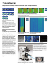
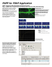
Others Graphic-based help, PAPP (Programmable Acquisition Protocol Processor), time course software (optional),
trigger IN/OUT function (optional), Multi point software (optional)
Power consumption Microscope (115V 6A/230V 3A), scanning unit+PSU (115V 3.5A/230V 2A), computer & monitor (115V 4.5A/230V 10A),
Ar laser (115V 10A/230V 5A), Mult-linei Ar laser (115V 10A/230V 5A), Kr laser (230V 20A),
HeNe laser each (115V 0.4A/230V 0.2A), LD laser (405nm, 440nm: 100V 0.9A/230V 0.5A)
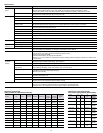
Specifications
Objective N.A. W.D. DIC Revolving
prism nosepiece
MPL5X 0.10 19.60 — WI-SSNP,
WI-SRE2
UMPLFL10XW 0.30 3.30 U-LDPW10H WI-SSNP,
WI-SRE2
UMPLFL20XW 0.50 3.30 U-LDPW20H WI-SSNP,
WI-SRE2
LUMPLFL40XW 0.80 3.30 U-LDPW40H WI-SSNP,
WI-SRE2
LUMPLFL60XW 0.90 2.00 U-LDPW60H WI-SSNP,
WI-SRE2
LUMPLFL40XW/IR 0.80 3.30 U-LDPW40H WI-SSNP,
WI-SRE2
LUMPLFL60XW/IR 0.90 2.00 U-LDPW60H WI-SSNP,
WI-SRE2
LUMPLFL100XW 1.00 1.50 U-LDPW60H WI-SSNP,
WI-SRE2
XLUMPLFL20XW 0.95* 2.00 U-LDPXLU20 WI-SNPXLU
HR
* Note: These conditions are not met in confocal microscopy
Condenser for BX Condenser for IX
Description Immersion Correction ring U-UCD8A IX-LWUCDA
optical element optical element
UPLSAPO 4X
0.16 13 —
UPLSAPO 10X
0.40 3.1 0.17 U-DIC10 IX2-DIC10 normal
UPLAPO 10XO3
0.40 0.24 0.17 Oil U-DIC10 IX2-DIC10 normal
UPLAPO 10XW3
0.40 0.43 0.17 Water U-DIC10 IX2-DIC10 normal
UPLSAPO 20X
0.75 0.6 0.17 U-DIC20 IX2-DIC20 normal
UPLAPO 20XO3
0.80 0.19 — Oil U-DIC20 IX2-DIC20 normal
UPLSAPO 40X
0.90 0.2 0.11-0.23 _ U-DIC40 IX2-DIC40 normal
UPLFLN 40XO
1.30 0.2 0.17 Oil U-DIC40 IX2-DIC40 normal
PLAPON 60XO
1.42 0.15 0.17 Oil U-DIC60 IX2-DIC60 BFP1
UPLSAPO 60XO
1.35 0.15 0.17 Oil U-DIC60 X2-DIC60 normal
UPLSAPO 60XW
1.20 0.28 0.15-0.2 Water _ U-DIC60 X2-DIC60 normal
UPLSAPO 100XO
1.40 0.12 0.17 Oil U-DIC100 X2-DIC100 normal
Objectives for BX and IX
(using U-UCD8, IX-LWUCDA and U-DICTS)
NA W.D
Cover glass
thickness
U-DICTS
position