5 - 31
5.4 Wiring
5.4.2 Spring clamp terminal block
5
SETTINGS AND PROCEDURES BEFORE
OPERATION
(b) Disconnecting a cable
1) For module power supply part/safety power supply part/safety input part/safety
output part terminal block
While fully pressing the open/close button with a flathead screwdriver, pull out
the cable.
2) For extension communication part terminal block
While fully inserting a flathead screwdriver into the open/close button, pull out
the cable from the insertion hole.
(2) Method for processing the cable end
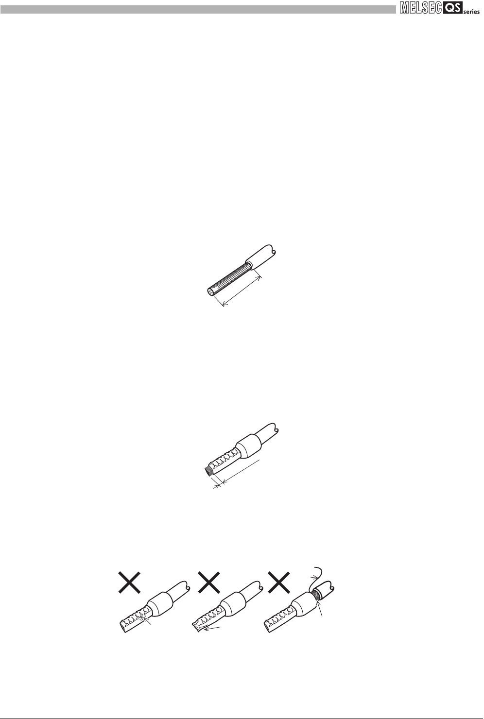
The cable strip length must be around 10mm (0.39 inch).
If the cable is stripped too much, conductive part may stick out of the terminal block,
which leads to electric shock or short-circuit between adjacent terminal blocks.
If the stripped length is too short, sufficient contact may not be ensured.
Figure 5.21 Cable strip length
For use of bar terminals, pay attention to the following:
1) Select a bar terminal suitable for the cable size.
2) Use an appropriate crimp tool to crimp the bar terminal.
3) Insert the cable so that cable cores will stick out by 0 to 0.5mm (0 to 0.02 inch)
from the sleeve edge.
Figure 5.22 Bar terminal
4) Check an appearance of the bar terminal after crimping it. Do not use the
terminal if it is not crimped properly or the side is damaged (refer to Figure
5.23).
Figure 5.23 Example of incorrect bar terminal crimp
Around 10mm
(0.39 inch)
Cable
Sleeve
Shell
Cable
0 to 0.5mm
(0 to 0.02 inch)
Damaged
Crushed edge
A cable is not
inserted to a shell.
Stray
wire


