


IMPORTANT!
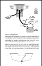
Make certain the red wire is fused. If the boat manufacturer installed your
unit, check the wiring and locate the 3001’s fuse holder. It should have a
1 amp fuse installed. If you purchased the 3001 from a dealer, a fuse
holder with fuse is supplied. Follow the wiring diagram carefully.
The unit won’t be harmed if the power wires are connected backwards,
however it won’t work until the wires are properly attached.
The black wire in the power cable is the negative or ground conductor.
Connect it directly to the battery’s negative terminal or the boat’s ground
buss.
The white wire is attached to the display’s backlight. You can attach this
wire to the power switch, a separate switch, or the boat’s main lighting
switch.
POWER CONNECTIONS (see diagram on the next page)
The 3001 operates from 10-15 VDC (12 volt battery). The power cable has
three wires - red, black, and white. The red wire is the positive conductor.
Connect it to an accessory switch.
2
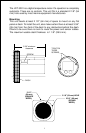
When you determine the location for the unit, drill a 2 1/8" (54 mm) hole
in the dash. Slide the unit through the hole from the front of the dash.
Align it so that it's straight, then tighten the two screws with a phillips-
head screwdriver.
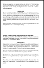
CAUTION!
To prevent damage to the unit, DO NOT use a pneumatic/power screw-
driver. Use a hand-held screwdriver and the torque should not exceed 7
in lbs. Also, when removing the unit, do not back the screws out of the
case. Damage to the faceplate will result. We recommend backing off
the screws one complete turn before attempting to remove the unit. If
further loosening of the screws is required, do so in half-rotation incre-
ments.
Place the bezel on the front of the unit and snap the bezel over the
faceplate. The unit is now ready for wiring.