


9
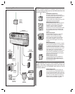
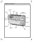
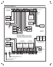
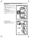
Relay Output Wiring
Any of the four relay outputs channels (A-D) can be used to control
access devices on doors or gates.
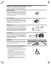
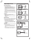
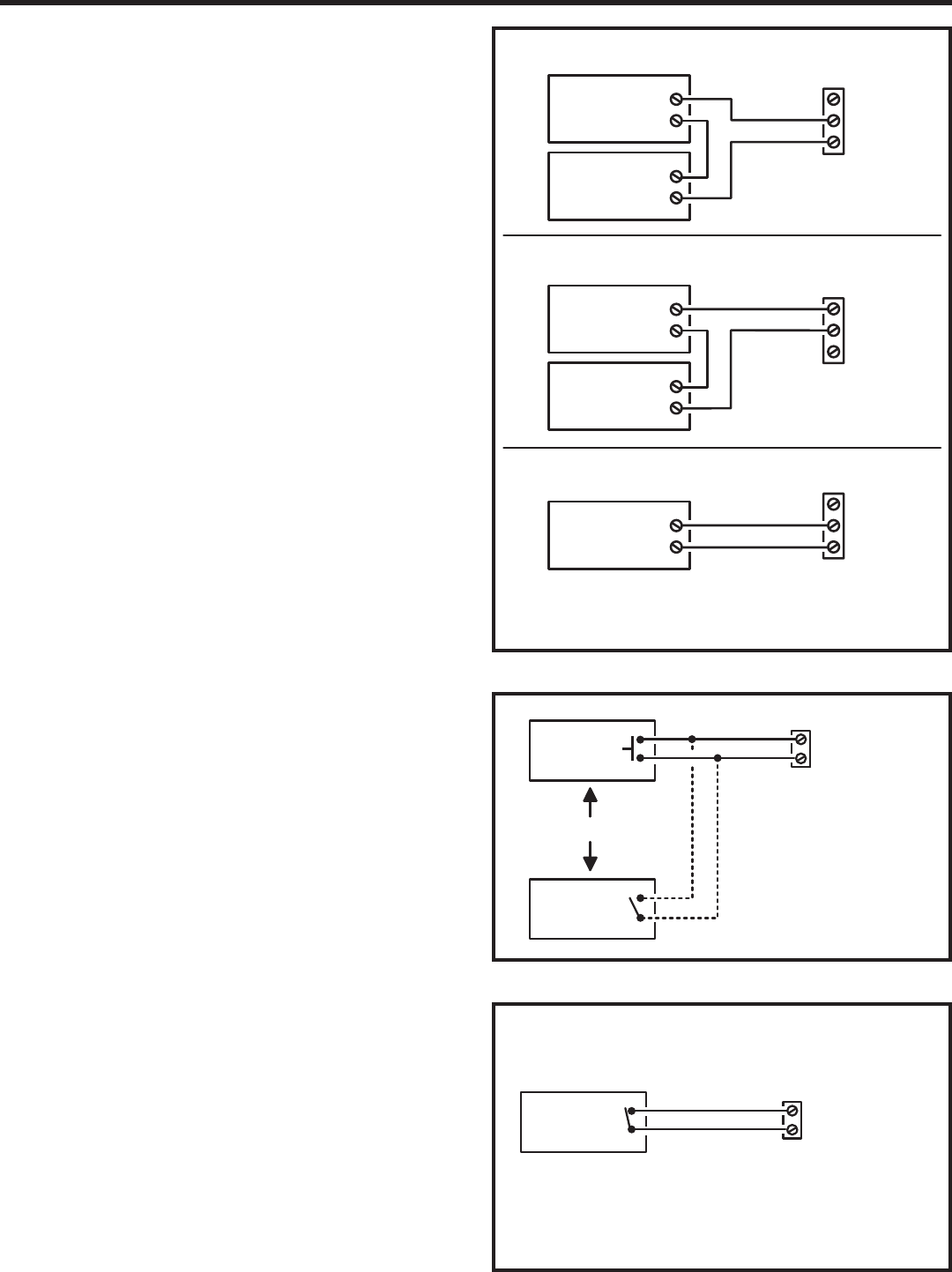
Door or Pedestrian Gate Control
1. Install a low voltage electric door strike or magnetic lock as a
locking device for the door or pedestrian gate.
2. Install the power supply or transformer for the locking device. DO
NOT POWER THE AM3Plus FROM THIS POWER SUPPLY.
3. Connect one wire from the power supply to one wire from the
locking device.
4. Route two wires between the locking device and the AM3Plus.
Connect one wire to the remaining wire of the locking device.
Connect the other wire to the remaining wire of the power supply.
5A. For a door strike, connect the wires to the AM3Plus relay COM &
N.O. terminals.
5B. For a magnetic lock, connect the wires to the AM3Plus relay COM
& N.C. terminals.
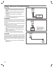
Gate Control
1. Route two wires between the gate and the AM3Plus.
2. Connect the gate operator’s OPEN terminals to the AM3Plus relay
COM & N.O. terminals.
✦ NOTE: For operator wiring specifi cs, refer to the gate operator’s
wiring diagram.
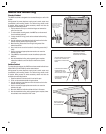
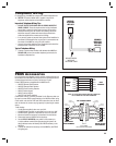
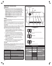
Request-to-Exit Inputs
Each of the four relay outputs has a request-to-exit input terminal.
Grounding this terminal will activate the associated relay. Exit request
inputs are typically used with push bars, loop sensors, or pushbuttons.
1. Install the pushbutton or device to signal an exit request.
2. Route two wires from the device to the AM3Plus.
3. Connect the device’s normally open output to the wires.
4. To activate a relay channel, connect the wires to the associated
relay request-to-exit terminal (RTE-A, RTE-B, RTE-C, or RTE-D)
and a GND terminal.
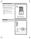
Sensing Inputs
The sensing inputs can connect to a door switch that monitors whether
the controlled door is open or closed.
1. To use the door sense feature to detect forced entry or door ajar
conditions, install a normally closed door switch on the door
or pedestrian gate and route two wires from the switch to the
AM3Plus.
2. Connect the sensing device wires to the associated relay sensing
terminal (DS-A, DS-B, DS-C, or DS-D) and a GND terminal.
N.O.
COM
N.C.
RELAY RATING:
3 AMPS @ 30 VOLTS
AC/DC MAXIMUM
TYPICAL DOOR STRIKE HOOKUP
TYPICAL MAGNETIC LOCK HOOKUP
TYPICAL AUTOMATIC GATE HOOKUP
ELECTRIC
DOOR
STRIKE
DOOR
STRIKE
POWER SUPPLY
N.O.
COM
N.C.
MAGNETIC
DOOR
LOCK
DOOR
LOCK
POWER SUPPLY
N.O.
COM
N.C.
GATE
OPERATOR
OPEN
RELAY
TERMINALS
CHANNEL A, B, C, OR D
RELAY
TERMINALS
CHANNEL A, B, C, OR D
RELAY
TERMINALS
CHANNEL A, B, C, OR D
GATE
EXIT LOOP
SENSOR
GND
RTE-A, B, C, OR D
REQUEST-TO-EXIT
TERMINALS
RTE = REQUEST-TO-EXIT
DOOR EXIT
REQUEST
BUTTON
OR
GND
DS-A, B, C, OR D
DOOR SENSE
TERMINALS
DS = DOOR SENSE
DOOR
SENSE
CONTACT
NOTE: DOOR
SENSE CONTACT
IS NORMALLY CLOSED