


8
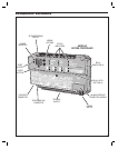
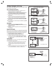
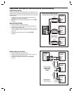
AM3Plus Mounting
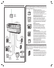
Standard Cabinet
The AM3Plus cabinet is designed to be mounted directly to a wall or fl at
surface.
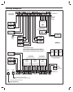
Wiring access for power, telephone, earth ground, control output must
be available at the mounting location. For easier wiring, choose a well
lit location. Wiring access for remote accessory cables must also be
available at the mounting location.
1. Flip the cabinet’s cover up to unlock the hinges and remove the
cover from the case.
2. To make cabinet mounting easier, the AM3Plus can be removed
from the cabinet (optional).
3. If using conduit for wiring, punch out the selected cabinet wiring
knockouts.
4. Use the cabinet as a template and mark the locations for the four
cabinet mounting screws in the keyhole slots.
5. Mark the wiring access slot if the wiring is being routed from
behind the cabinet.
6. Use a hole saw to cut out the location for the wiring access slot (if
used).
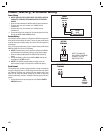
7. Use four screws and appropriate screw anchors to mount the
cabinet to the wall.
8. If the AM3Plus was removed to mount the cabinet, replace the
AM3Plus.
9. After the installation’s wiring and programming are complete,
replace the cabinet’s cover and secure it with the two screws
provided.
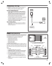
Outdoor Cabinet
To protect the unit outdoors, the AM3Plus can be mounted inside a Linear
Model CAB-3 (P/N ACP000913) outdoor metal cabinet.
Wiring access for power, telephone, earth ground, control output must
be available at the mounting location. For easier wiring, choose a well
lit location. Wiring access for remote accessory cables must also be
available at the mounting location.
1. Open the cabinet’s cover and push it in to latch it open.
2. Punch out the selected cabinet wiring knockouts.
3. Use the cabinet as a template and mark the locations for the four
cabinet mounting screws.
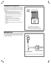
4. Use four screws and appropriate screw anchors to mount the
cabinet to the wall.
5. Mount the AM3Plus inside the cabinet with four 6-32 screws.
6. After the installation’s wiring and programming are complete, lower
the cabinet’s cover and secure it with a lock.
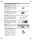
USE THE CABINET BOTTOM AS
A TEMPLATE TO MARK THE
FOUR KEYHOLE MOUNTING
HOLES
FOR RECESSED WIRING,
MARK WIRING SLOT,
THEN CUT OUT HOLE
WITH DRYWALL SAW
FOR CONDUIT WIRING,
REMOVE ANY CABINET
KNOCKOUTS BEFORE
MOUNTING THE CABINET
USE THE APPROPRIATE
HARDWARE TO MOUNT
THE CABINET
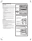
FOR CONDIUT WIRING,
PUNCH OUT REQUIRED
KNOCKOUTS AND
INSTALL 3/4" CONDUIT
HUBS IN HOLES
CONDUIT
KNOCKOUTS
AM3PLUS MOUNTS IN
CAB-3 CABINET WITH
FOUR 6-32 SCREWS
CAB-3 CABINET