


16
System Controls
Pushbuttons
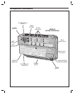
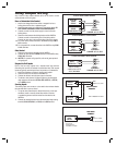
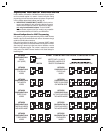
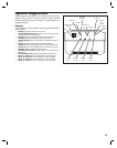
Refer to the fi gure for the location of each of the eight pushbuttons.
• UP button adds one to the value on the STATUS/PROGRAM display.
• DOWN button subtracts one from value on the STATUS/PROGRAM display.
Press with the UP button for one second to enter Programming Mode.
• ENTER button accepts the value on the STATUS/PROGRAM display
during programming, clears an indication during the supervisory display.
• RELAY “A” LATCH press to latch relay “A”, press again to unlatch.
• RELAY “B” LATCH press to latch relay “B”, press again to unlatch.
• RELAY “C” LATCH press to latch relay “C”, press again to unlatch.
• RELAY “D” LATCH press to latch relay “D”, press again to unlatch.
• SYSTEM RESTART BUTTON will reboot the system’s microcontroller. NO
SYSTEM INFORMATION WILL BE ERASED.
Display
The STATUS/PROGRAM display will shows the current system conditions
and is used for system setup.
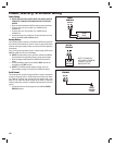
Power-up
When power is applied, the display will show the current mode of operation
(AXNET “An” or AccessBase2000 “Ab”) and the version number of the
fi rmware installed. The default mode of operation is AccessBase2000.
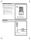
Program Mode
Program Mode uses the display and the UP, DOWN, and ENTER
pushbuttons. The setting the network node address, operation mode, and
clearing the memory can be performed in Program Mode.
Refer to the following steps to change the system settings:
1. To enter Program Mode, press and hold the UP and DOWN
pushbuttons together for one second. While in Program Mode, both
decimal points on the display are lit.
2. The display shows the current network node number setting.
3. Press the UP or DOWN button to cycle the display through the
options that can be selected (see Program Mode Display Table).
4. When the desired option is displayed, press the ENTER button to
select the option.
✦ NOTE: In network installations, a unique network address
(1-8 for AccessBase2000, 1-4 for AXNET) must be set before
communicating with network.
✦ NOTE: If using AXNET for programming the system, select the
An programming option, for AccessBase2000 select Ab.
After the option is selected, the system will restart.
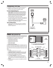
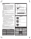
Status Mode
While the system is running, the display will show the current system
status. Normally the left digit will show a moving pattern and the right digit
will show the unit’s Network Node number.
When a supervisory condition exists, the display will cycle to show the
condition(s). When an item is displayed, press the ENTER button to clear
the display (clears the display only, the condition may still exist). Refer to
the following table for the supervisory condition display codes.
STATUS MODE DISPLAY
DISPLAY CONDITION
01 MGT TRANSMITTER STATUS EXCEPTION
02 MGT TRANSMITTER LOW BATTERY
03 MGT TRANSMITTER TAMPER
04 AC POWER FAIL (BACKUP BATTERY REQUIRED)
05 CHANNEL “A” LOCKED CLOSED
06 CHANNEL “B” LOCKED CLOSED
07 CHANNEL “C” LOCKED CLOSED
08 CHANNEL “D” LOCKED CLOSED
09 MODEM FAILURE
STATUS/PROGRAM
DISPLAY
"ENTER"
BUTTON
"UP"
BUTTON
"DOWN"
BUTTON
RELAY "A"
LATCH
RELAY "B"
LATCH
RELAY "C"
LATCH
RELAY "D"
LATCH
SYSTEM
RESTART
BUTTON
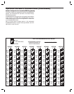
PROGRAM MODE DISPLAY
AccessBase2000 MODE AXNET MODE FUNCTION
0.1. 0.1. SET UNIT TO NODE #1
0.2. 0.2. SET UNIT TO NODE #2
0.3. 0.3. SET UNIT TO NODE #3
0.4. 0.4. SET UNIT TO NODE #4
0.5. SET UNIT TO NODE #5
0.6. SET UNIT TO NODE #6
0.7. SET UNIT TO NODE #7
0.8. SET UNIT TO NODE #8
A.N. A.b. SWITCH OPERATION MODE
B.L. B.L. RESERVED (DO NOT USE)
C.L. C.L. CLEAR UNIT’S MEMORY
SYSTEM IDLE
LEFT DIGIT CIRCULATES
RIGHT DIGIT SHOWS NETWORK NODE ADDRESS
DIGITS SHOW SUPERVISORY CODE
STATUS MODE
STATUS/PROGRAM
DISPLAY
DECIMAL POINTS LIGHT, DIGITS SHOW PROGRAMMING OPTION
PROGRAM MODE