


22
23
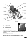
8.4 Forks and Front wheels
- The front castors either have a diameter of 8’’ x 1.3/8’’ (200 mm x 32 mm)
or 8 ‘’ x 2’’ (200 mm x 50 mm) or 6’’ x 1.3/8’’ (150 mm x 32 mm) can be fitted
with pneumatic or solid tyres.
- Adjustment : Only the pneumatic tyre may require pressure verification.
The pressure is shown on the sidewall and the tyre must never be over
inflated.
A pump is supplied with the wheelchair.
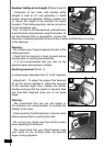
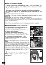
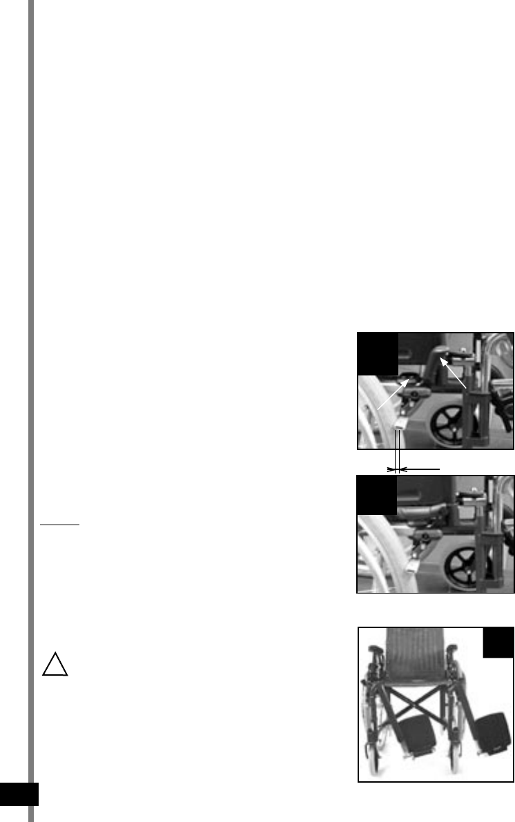
Whenever a tyre is flat, it may be necessary to remove the tyre from its rim.
(photo 12)
Force the air out the the inner tube by pressing valve A.
Stretch the outer case on the rim. Repair or replace the inner tube. Put the
inner tube back in place. Reposition the outer case on the rim. Re-inflate the
tyre to specified pressure.
Note : It may be necessary to use one or two tyre-levers (Not supplied).
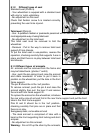
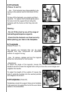
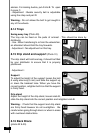
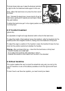
8.5 Manual brakes (Photos 13A and 13B)
The manual brakes are designed to secure the
wheelchair during long stops. They are not
intended to slow down the wheelchair or to be used
as support during a transfer.
They must be operated simultaneously.
In order to brake, push the handle (A) forward.
The handle folds back to facilitate transfers. Draw
as a preliminary the handle upwards ! (13A)
Once the brakes are engaged, the wheelchair
should not move at all.
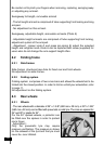
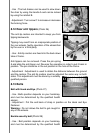
Note :
brakes adjustments are based upon the dia-
meter and type of the wheels. After repairing a at
tyre or in the event of wear of the pneumatic or solid
tyre, you may need to adjust the brake(s). To adjust
the brake(s), loosen the two screws (B) and slide
the brake assembly to obtain the following value
between the wheel and the brake shoe in unlocked position :
Solid tyre X = 6 mm, Pneumatic tyre X = 5 mm
!
Firmly tighten the screws (B) after adjustment.
Keep your ngers away from movable parts to pre-
vent injuries !
14
13B
13A
A
B
X