


47
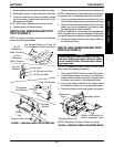
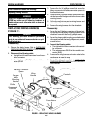
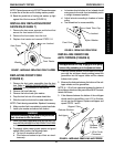
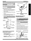
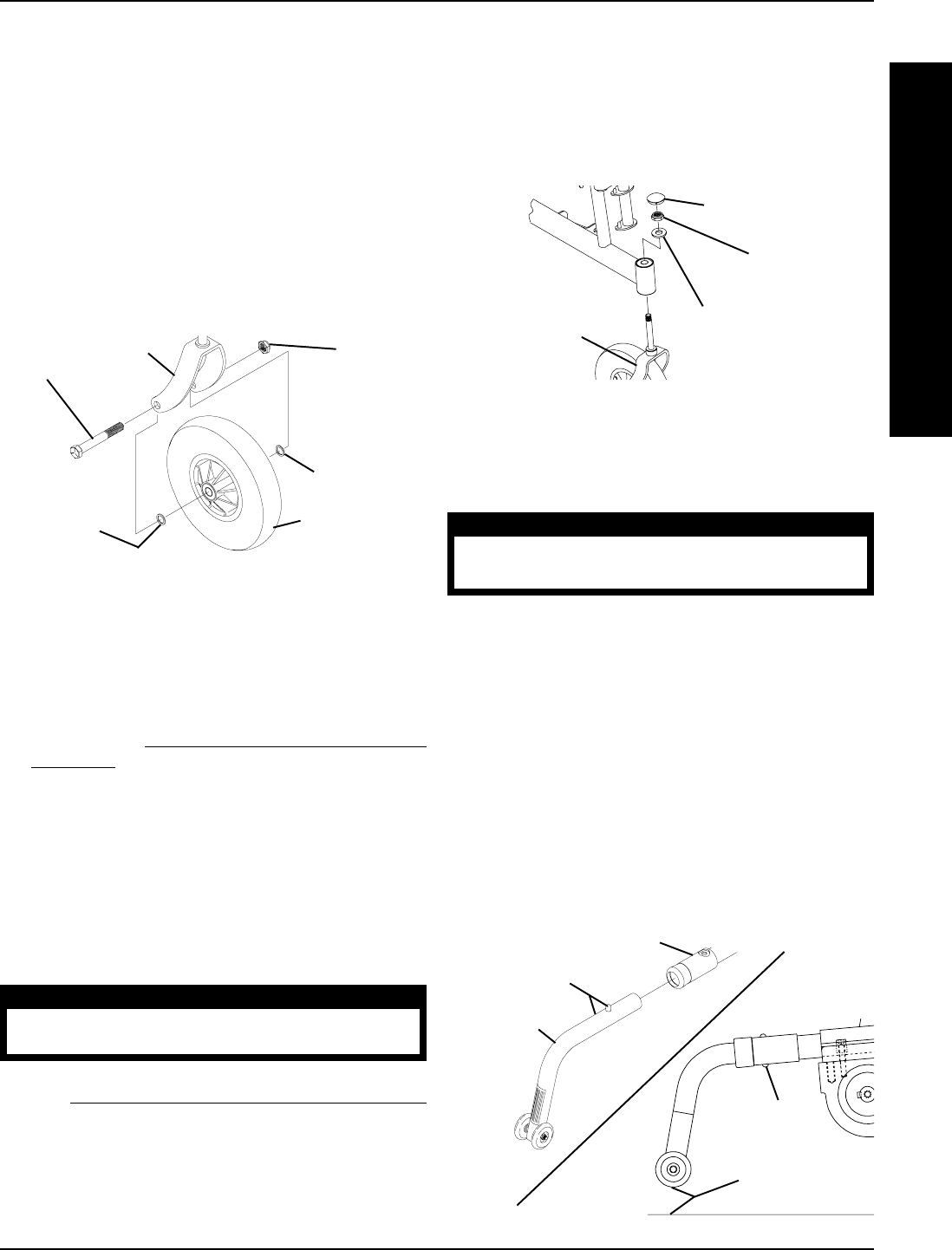
FIGURE 9 - INSTALLING/REMOVING ANTI-TIPPERS
1-1/2 to 2-inch
Clearance
Release
Buttons
Release Buttons
Support Tube
Anti-tipper
INSTALLING/REMOVING
ANTI-TIPPERS (FIGURE 9)
WARNING
Anti-tippers MUST be fully engaged and spring
buttons fully protruding out of adjustment holes.
1. Press the release buttons IN and insert the anti-tip-
pers with the anti-tipper wheels pointing toward the
ground/floor into the support tubes until the release
buttons lock in place.
2. Measure the distance between the bottom of the anti-
tipper wheels and the ground/floor.
NOTE: A 1-1/2 to 2-inch clearance between the bottom of
the anti-tipper wheels and the ground/floor MUST be main-
tained at all times.
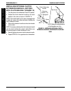
3. If the distance between the bottom of the anti-tipper
wheels and the ground/floor is not 1/1/2 to 2-inches,
do not use the anti-tippers. Replace anti-tippers and
repeat STEPS 1 and 2.
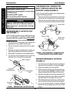
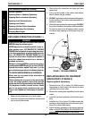
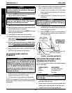
REPLACING FRONT FORK
(FIGURE 8)
1. Remove the front caster assemblies from the front
fork. Refer to
INSTALLING/REPLACING FRONT
CASTERS in this procedure of the manual.
2. Remove the head tube cap.
3. Remove the locknut and nylon washer.
4. Drop the front fork out of the caster head tube.
5. Slide the new front fork into the caster head tube.
NOTE: Check bearing assemblies. Replace if necessary.
6. Make sure front fork is completely in caster head tube.
7. Install nylon washer and secure with locknut.
WARNING
Improper positioning of the washer will prohibit the
free movement of the front forks.
8. Install front caster assemblies onto the front fork. Re-
fer to
INSTALLING/REPLACING FRONT CASTERS
in this procedure of the manual.
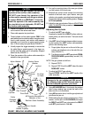
9. To properly tighten caster journal system and guard
against flutter, perform the following check:
a. Tip front of wheelchair off floor.
b. Pivot forks and casters to top of their arc simul-
taneously.
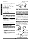
Head Tube Cap
Locknut
Nylon Washer
Front Fork
FIGURE 8 - REPLACING FRONT FORK
NOTE: Tighten hex screw only. DO NOT loosen hex screw
to make one of the tabs on the locking washer parallel.
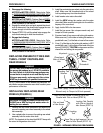
10. Bend the parallel tab of locking tab washer up tight
against flat of the hex screw (FIGURE 6).
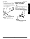
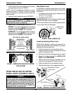
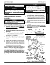
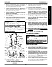
INSTALLING/REPLACING FRONT
CASTERS (FIGURE 7)
1. Remove the hex screw, spacers and locknut that
secure the front caster to the fork.
2. Remove the front caster from the fork.
3. Replace front caster and reverse STEPS 1-2.
Hex Screw
Locknut
Fork
Washer
Washer
Front Caster
FIGURE 7 - INSTALLING/REPLACING FRONT CASTERS
c. Let casters drop to bottom of arc (wheels should
swing once to one-side, then immediately rest in
a straight downward position).
d. Adjust locknuts according to freedom of caster
swing.
e. Test wheelchair for maneuverability.
W
H
E
E
L
S
/
A
N
T
I
-
T
I
P
P
E
R
PROCEDURE 12WHEELS/ANTI-TIPPER