


13
CALL TOLL FREE, 1-888-6AURORA
(628-7672)
QUESTIONS ABOUT THIS PRODUCT?
This Procedure includes the following:
Swingaway Footrest Assembly Installation
Swingaway Footrest Height Adjustment
Heel Loop Replacement
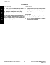
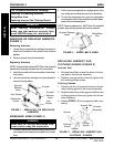
1. Remove the hex screw and coved washer that se-
cure the lower footrest assembly to the upper foot-
rest support.
2. Reposition the lower footrest assembly to the desired
height. Line up the mounting holes in the lower foot-
rest assembly and the upper support.
3. Securely tighten the hex screw and coved washer.
4. Repeat this procedure for the other footrest, if neces-
sary.
PROCEDURE 1FOOTRESTS
WARNING
After making adjustments, always make
sure that parts are properly tightened BE-
FORE using the wheelchair.
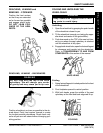
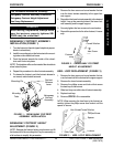
SWINGAWAY FOOTREST ASSEMBLY
INSTALLATION (FIGURE 1)
1. Turn the footrest to the side (open footplate is perpen-
dicular to wheelchair).
2. Install the mounting pin on the footrest onto the mount-
ing tube on the wheelchair frame.
3. Push the footrest towards the inside of the wheel-
chair until it locks into place.
NOTE: The footplate will be on the inside of the wheelchair
when locked in place.
4. Repeat this procedure for other footrest assembly.
5. To release the footrest, push the footrest release le-
ver inward, rotate footrest outward.
SWINGAWAY FOOTREST HEIGHT
ADJUSTMENT (FIGURE 2)
NOTE: Release the footrest locking mechanism and lift
the footrest off of the mounting tube. Lay the assembly on
a flat surface to simplify this procedure.
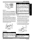
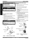
FIGURE 1 - SWINGAWAY FOOTREST
ASSEMBLY INSTALLATION
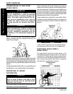
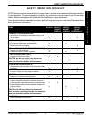
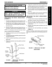
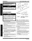
Hex Screw/Coved Washer
Phillips Screw
Spacer
Locknut
FIGURE 3 - HEEL LOOP REPLACEMENT
Mounting Pin
Footrest
Release
Lever
Mounting
Tube
Swingaway
Footrest
Assembly
Slide Tube
HEEL LOOP REPLACEMENT (FIGURE 3)
1. Remove the hex screw and coved washer that se-
cure the lower half of the footrest to the upper support.
2. Remove the lower footrest assembly.
3. Remove the phillips screw and locknut that secure
the heel loop to the footrest.
4. Slide heel loop over slide tube of footrest assembly.
5. Replace heel loop.
6. Reverse STEPS 1-5 to reassemble.
NOTE: When securing the heel loop to the footrest as-
sembly, tighten the phillips screw and locknut until the
spacer is secure.
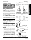
Hex Screw
Coved Washer
Footrest
FIGURE 2 - SWINGAWAY FOOTREST
HEIGHT ADJUSTMENT
F
O
O
T
R
E
S
T
S