SECTION 4—FRONT CASTERS
Part No. 1076155 27 9000 Series
Converting from Trailing to Leading or Leading to
Trailing Casters
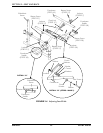
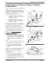
NOTE:Forthisprocedure,refertoFIGURE4.2.
Adjustingthecasterheadtubeposition
(leadingortrailing)changesthewheelbase
lengthofthewheelchair.Therearetwo(2)
adjustmentswhichallowfora:
•Longerwheelbase‐Thecaster
headtubeisleadingorinfrontofthe
wheelchairframe.
•Shorterwheelbase‐Thecaster
headtubeistrailingorbehindthe
wheelchairframe.
NOTE:Ifthecasterheadtubesarepositionedin
theleadingpositionwhenusing8‐inchcasters,
a60°footrestisrecommendedtoallow
adequateroomforfeetandcasterswivel.
NOTE:Makenoteoftheorientationofthecam
forproperreinstallation.Ifchangingthe
seat‐to‐floorheightand/ortheseat‐to‐floor
angle,refertoChangingSeat‐to‐Floor
Height/Seat‐to‐FloorAngleonpage 29.
1. Removethetwo(2)mountingscrews,
covedspacer,washer,camandtwo(2)
locknutsthatsecuretheinsertandthe
casterheadtubetothewheelchair
frame.
NOTE:Theinsertwilldropifitisnotcaught.
2. RepeatSTEP1foroppositeside.
3. Positiontheexistingrightcaster
headtubeontothe
leftwheelchair
frame.
NOTE:Ensuretheinsertispositionedintothe
bottomofthewheelchairframewiththe
mountingholesalignedwiththeframe
mountingholes.
4. Ensurecovedspacerisproperly
positionedwiththeroundedendup.
Thecut‐out(Detail“A”)onthe
undersideofthecovedspacershould
cleartheframejoint.
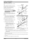
FIGURE 4.2 Converting from Trailing to
Leading or Leading to Trailing Casters
Washer
Cam
Locknuts
Coved
Spacer
Caster
Headtube
Insert
Mounting
Screws
Wheelchair Frame
Leading
Trailing
Wheelchair
Frame
Frame Joint
Coved Spacer
Cam
Locknuts
Washer
Caster Headtube
Insert
Mounting
Screws
DETAIL “A” - COVED SPACER
Rounded
End
Cut-out on
Underside of
Coved Spacer
Frame
Mounting
Holes
Frame
Mounting
Holes


